
Protection circuit of electric vehicle charging controller

A charging controller and protection circuit technology, used in emergency protection circuit devices, electric vehicles, battery circuit devices, etc., can solve the problems of inability to monitor, inconvenient use, uneven geographical distribution, etc., to achieve the safety of the charging process and avoid charging interruptions , to ensure the effect of continuity

Active Publication Date: 2014-11-12
ZHANGJIAGANG UCHEN NEW ENERGY TECH CO LTD
View PDF9 Cites 11 Cited by
  • Summary
  • Abstract
  • Description
  • Claims
  • Application Information

AI Technical Summary

Problems solved by technology

The so-called imperfect charging facilities, one means that there are too few charging stations and charging piles for charging electric vehicles, and the geographical distribution is extremely uneven; the other means that the design of charging equipment, that is, charging controllers is not reasonable enough
Here, only the charging controller is discussed. The current charging controller usually only has some simple protection circuits such as over-current and over-voltage. During the working process of the charging controller, the degree of leakage and over-current cannot be checked. And many other abnormal situations are fully monitored; moreover, once a fault occurs, the entire charge controller has to be restarted, which is very inconvenient to use

Method used


Image

  • Protection circuit of electric vehicle charging controller
  • Protection circuit of electric vehicle charging controller
  • Protection circuit of electric vehicle charging controller

Examples


Embodiment approach

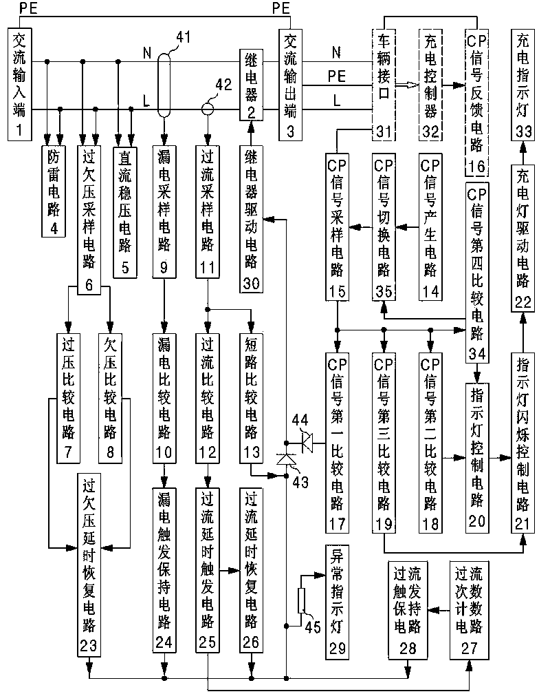
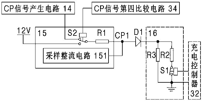
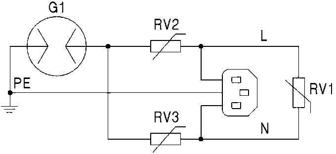
[0045] Such as figure 1 As shown, a protection circuit for an electric vehicle charging controller according to the present invention includes an AC input terminal 1, a relay 2 as a switch, an AC output terminal 3, a lightning protection circuit 4, and a circuit for providing a 12V working voltage DC voltage stabilization circuit 5, overvoltage and undervoltage sampling circuit 6, overvoltage comparison circuit 7, undervoltage comparison circuit 8, leakage sampling circuit 9, leakage comparison circuit 10, overcurrent sampling circuit 11, overcurrent comparison circuit 12, short circuit comparison circuit 13. The pulse signal generating circuit is the CP signal generating circuit 14, the pulse signal sampling circuit is the CP signal sampling circuit 15, the pulse signal feedback circuit is the CP signal feedback circuit 16, the pulse signal first comparison circuit is the CP signal first comparison circuit 17, The pulse signal second comparison circuit is the second CP signal...


PUM


Abstract

The invention discloses a protection circuit of an electric vehicle charging controller. The charging process can be safe and stable by means of the protection circuit. The protection circuit comprises the alternating current input end, the alternating current output end, an on-off device, an overvoltage and undervoltage sampling circuit, an overvoltage comparison circuit, an undervoltage comparison circuit, an overvoltage and undervoltage time delay restoring circuit, an electric leakage sampling circuit, an electric leakage comparison circuit, an electric leakage trigger retaining circuit, an overcurrent comparison circuit, an overcurrent time delay trigger circuit, an overcurrent time delay restoring circuit, a short circuit comparison circuit, a clock pulse signal producing circuit, a clock pulse signal sampling circuit, a clock pulse signal first comparison circuit and an on-off driving circuit. The on-off driving circuit drives the on-off device according to signals output by the overvoltage and undervoltage time delay restoring circuit, the electric leakage trigger retaining circuit, the overcurrent time delay trigger circuit and the clock pulse signal first comparison circuit to connect or disconnect the alternating current input end with the alternating current output end. The protection circuit is particularly suitable for being used in cooperation with an automobile charging controller.

Description

technical field [0001] The invention relates to a circuit structure, in particular to a pure hardware circuit structure, and in particular to a protection circuit for a charging controller of an electric vehicle. Background technique [0002] At present, electric scooters are in the ascendant, and electric vehicles are booming even more. As various electric vehicles continue to enter ordinary people's homes, the problem of imperfect charging facilities is becoming more and more prominent, which seriously restricts the popularization of electric vehicles, especially electric vehicles. The so-called imperfect charging facilities, one means that there are too few charging stations and charging piles for charging electric vehicles, and the geographical distribution is extremely uneven; the other means that the design of charging equipment, that is, charging controllers is not reasonable. Here, only the charging controller is discussed. The current charging controller usually on...

Claims


Application Information

Patent Timeline
Patent Type & Authority Applications(China)
IPC IPC(8): H02J7/00H02H7/00
Inventor 王友锋郑晓波陈建刚
Owner ZHANGJIAGANG UCHEN NEW ENERGY TECH CO LTD
Learn More