Supercharge Your Innovation With Domain-Expert AI Agents!

Exhaust gas feed device for an internal combustion engine

A technology of exhaust gas introduction and internal combustion engine, applied in the direction of internal combustion piston engine, exhaust gas recirculation, combustion engine, etc., can solve the problems of high pressure loss, no mixing, exhaust gas pipeline pulsation and difficult adjustment of pressure difference, etc. Effects of reduced space, reduced temperature spikes, simple installability

Inactive Publication Date: 2014-11-12
PIERBURG GMBH & CO KG NEUSS
View PDF11 Cites 11 Cited by
  • Summary
  • Abstract
  • Description
  • Claims
  • Application Information

AI Technical Summary

Problems solved by technology

[0005] In such mixing by static mixers it may happen that the streams of gas within the pre-existing gas mixture reverse in the same way as the surrounding gas so that good mixing does not occur thereafter
Whereas with mixing by radial introduction there is on the one hand relatively good mixing but on the other hand a high pressure loss
[0006] In addition, the flow regulation of the incoming exhaust gas flow is located far away from the point of introduction, making it difficult to precisely regulate the pulsations and pressure differences in the subsequent exhaust gas line

Method used


Image

  • Exhaust gas feed device for an internal combustion engine
  • Exhaust gas feed device for an internal combustion engine

Examples


Embodiment Construction

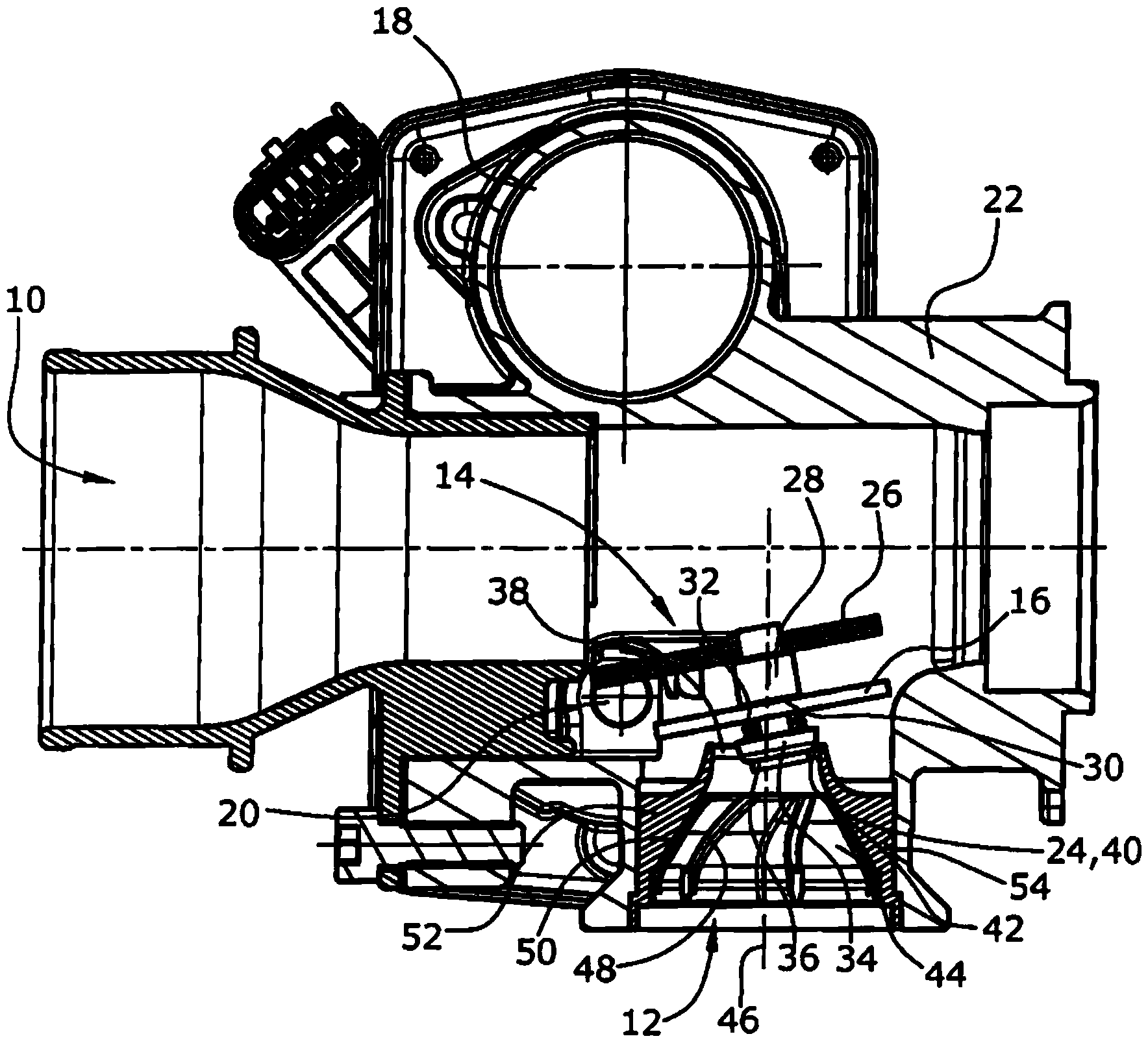
[0021] The exhaust gas introduction device according to the present invention includes an air suction passage 10 in which air used for combustion in an internal combustion engine is sucked in the direction of the compressor of the turbocharger through a filter on the upstream side of the flow not shown. The returned exhaust gas is introduced into the air suction passage 10 in the low-pressure exhaust gas return part before the compressor.

[0022] This is done through the exhaust gas return passage 12, which in this embodiment opens into the air suction passage 10 at right angles to the air suction passage 10. The amount of returned exhaust gas is adjusted by an exhaust gas return valve 14 whose regulating body is formed by an eccentrically supported plate 16 in this embodiment.

[0023] The exhaust gas return valve 14 has an actuator 18 in the form of an electric motor followed by a transmission through which a shaft 20 used as a rotating shaft rotates. This shaft 20 is supported...


PUM


Abstract

The invention relates to an exhaust gas feed device for an internal combustion engine, comprising an exhaust gas recirculation duct (12), an air intake duct (10) into which said exhaust gas recirculation duct (12) opens, and a flow-guiding element (44) that is arranged in, and at one end (42) of, said exhaust gas recirculation duct (12). Quantity regulation for an exhaust gas flow afflicted with turbulence is unknown, and it is therefore suggested that a valve seat (40) is designed at an outlet (24) at the end (42) of the exhaust gas recirculation duct (12) in which the flow-guiding element (44) is arranged, said valve seat delimiting an exhaust gas recirculation duct (12) outflow cross-section (38), controlled by a regulator body (16) of an exhaust gas recirculation valve (14).

Description

Technical field [0001] The present invention relates to an exhaust gas introduction device for an internal combustion engine, which is provided with an exhaust gas return passage, an air suction passage into which the exhaust gas return passage opens, and a flow guide element arranged in the exhaust gas return passage at one end of the exhaust gas return passage. Background technique [0002] Such exhaust gas introduction equipment is known and described in multiple applications. The purpose of this introduction device is to ensure good mixing of the exhaust gas flow and the air flow. However, it should be noted that a sufficient pressure drop should also be maintained in the exhaust gas return channel, so that a sufficient amount of exhaust gas can be returned. Accordingly, greater pressure loss is avoided. [0003] In addition to this introduction device formed for example by a channel wall with slits-the exhaust gas can flow radially from the surrounding annular channel into t...

Claims


Application Information

Patent Timeline
Patent Type & Authority Applications(China)
IPC IPC(8): F02M25/07F02M35/10
CPCF02M25/079F02M25/0788Y02T10/146Y02T10/121F02M35/10222F02M25/0724F02M25/0722F02M26/19F02M26/21F02M26/54F02M26/66F02M26/68Y02T10/12
Inventor C.安托尼B.布罗尼谢夫斯基W.柯南
Owner PIERBURG GMBH & CO KG NEUSS
Features
  • R&D
  • Intellectual Property
  • Life Sciences
  • Materials
  • Tech Scout
  • Unparalleled Data Quality
  • Higher Quality Content
  • 60% Fewer Hallucinations
Learn More