Double-milling head machining device

A technology of machining and milling head, applied in metal processing equipment, milling machine, milling machine equipment, etc., can solve the problem of difficulty in ensuring the relative position accuracy of each group of holes or grooves, inability to ensure the coincidence of the needle bed and needle core bed, and low processing efficiency. problems, to achieve the effect of expanding the range of processing, low labor intensity and high processing efficiency

Active Publication Date: 2014-11-19
CHANGLE WANDA TEXTILE MACHINERY
View PDF8 Cites 0 Cited by
  • Summary
  • Abstract
  • Description
  • Claims
  • Application Information

AI Technical Summary

Problems solved by technology

[0002] The traditional machine tool has only one milling head. If two groups of holes, slots or others with different specifications and corresponding positions are to be processed (the number of holes and slots in each group is large and the distribution size is long), it is difficult for the traditional machine tool to guarantee each milling head. Relative positional accuracy of groups of holes or slots
For example, the needle bed and the needle core bed on the textile machinery, the distance between the needle bed and the needle core bed is as long as 5 to 10 meters, and some are even longer. The grooves of different specifications are extended and arranged in sequence in the length direction. In order to meet the assembly requirements, the center of each group of corresponding grooves on the needle bed and the needle core bed must coincide. The traditional machine tool must first install the needle bed on the workbench, and the needle bed is processed. After the groove on the bed, install the core bed on the workbench, and replace the tool to process the groove on the core bed. This not only reduces the processing efficiency, but also cannot ensure that the centers of the corresponding grooves on the needle bed and the needle core bed coincide

Method used


Image

  • Double-milling head machining device
  • Double-milling head machining device
  • Double-milling head machining device

Examples


Embodiment Construction

[0025] The content of the present invention will be described in detail below in conjunction with the accompanying drawings and specific embodiments of the description:

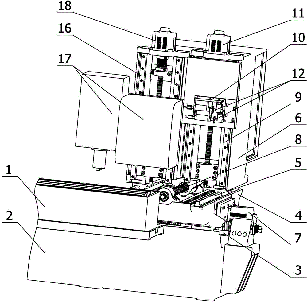
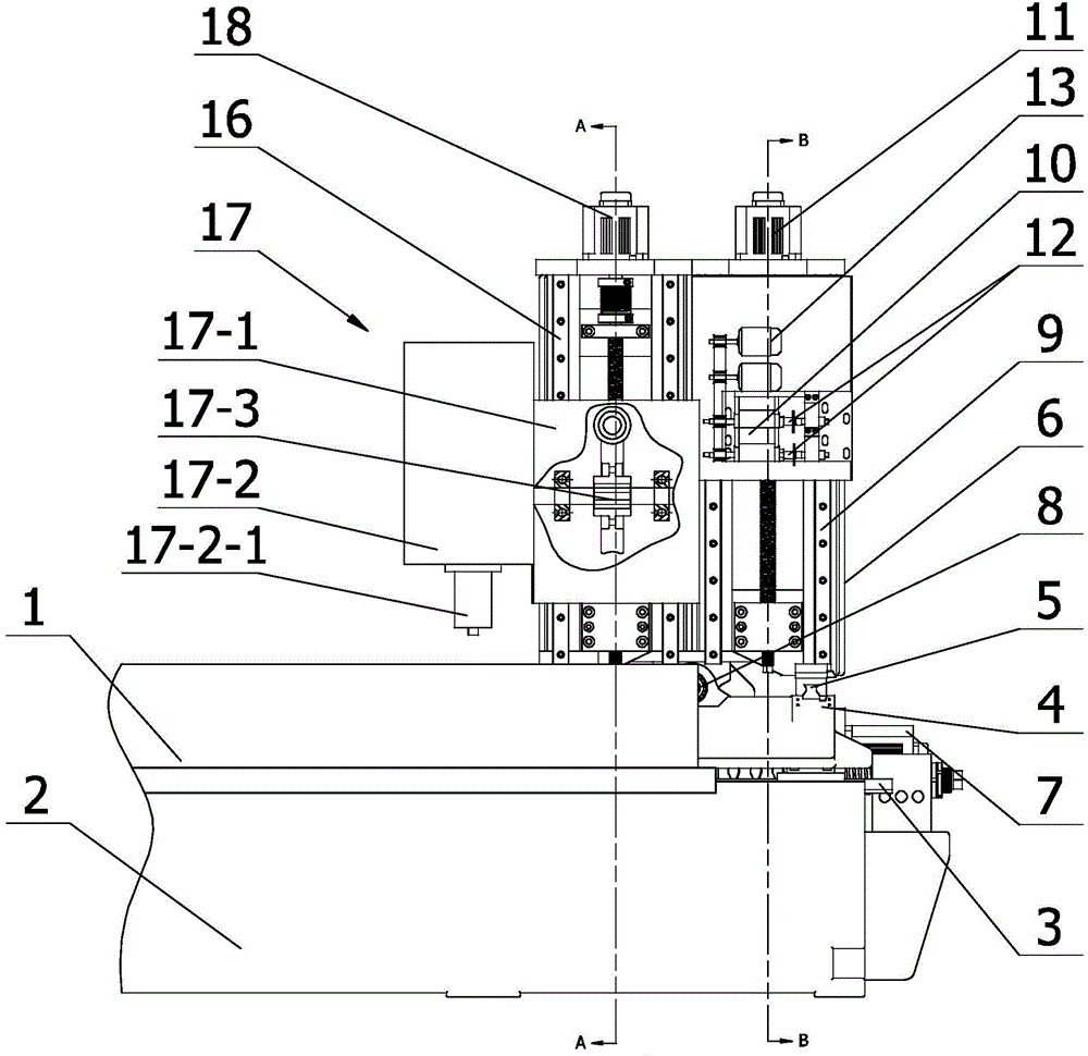
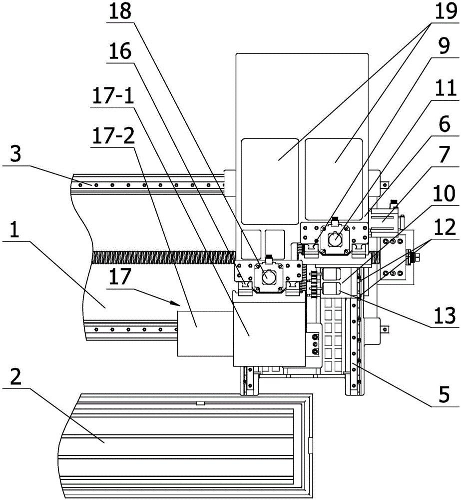
[0026] Such as Figure 1-Figure 8 Shown is the double milling head machining device provided by the present invention. Such as figure 1 As shown, the device includes a worktable 1 arranged along the X-axis direction, an X-axis bed 2 parallel to the worktable 1, an X-axis guide rail pair 3 arranged on the upper surface of the X-axis bed 2 along the X-axis direction, and a lower surface The tray 4 slidingly connected with the X-axis guide rail pair 3, the Z-axis guide rail pair 5 arranged on the upper surface of the tray 4 along the Z-axis direction, the column 6 slidingly connected above the Z-axis guide rail pair 5, and the drive tray 4 along the X-axis guide rail pair 3 The X-axis drive device 7 sliding in the X-axis direction and the Z-axis drive device 8 for driving the column 6 to slide along the Z-axis...


PUM


Abstract

The invention relates to a double-milling head machining device. The device comprises a working table, an X-axle machine body, an X-axle guide rail pair, a tray, a Z-axle guide rail pair, a stand column, an X-axle driving device and a Z-axle driving device, wherein a Y-axle guide rail pair 1 is arranged on the stand column, and is in sliding connection with a horizontal milling head mounting base; a Y1-axle driving device is additionally mounted on the stand column; two cutter shafts with parallel axles in an X-axle direction and rotationally connected to the horizontal milling head mounting base and cutter shaft driving devices for driving the cutter shafts to rotate are arranged on the horizontal milling head mounting base; the positions of the two cutter shafts in a Y-axle direction and a Z-axle direction are staggered from each other; and the distance from the cutter shaft at the lower side in the Y-axle direction to the working table is further in the Z-axle direction. The device can guarantee the position preciseness of each set of corresponding machining positions of two workpieces having the machining position cooperative relationship, and has the prominent advantages of high machining efficiency and low labor intensity.

Description

technical field [0001] The invention relates to a machining device, in particular to a machining device with double milling heads. Background technique [0002] The traditional machine tool has only one milling head. If two groups of holes, slots or others with different specifications and corresponding positions are to be processed (the number of holes and slots in each group is large and the distribution size is long), it is difficult for the traditional machine tool to guarantee each milling head. Relative positional accuracy of groups of holes or slots. For example, the needle bed and the needle core bed on the textile machinery, the distance between the needle bed and the needle core bed is as long as 5 to 10 meters, and some are even longer. The grooves of different specifications are extended and arranged in sequence in the length direction. In order to meet the assembly requirements, the center of each group of corresponding grooves on the needle bed and the needle ...

Claims


Application Information

Patent Timeline
Patent Type & Authority Applications(China)
IPC IPC(8): B23C1/10
Inventor 李洪春
Owner CHANGLE WANDA TEXTILE MACHINERY
Why Eureka
Try Eureka