A ventable die

A technology of dies and exhaust grooves, applied in glass forming, glass blowing, glass manufacturing equipment, etc., can solve problems such as glass frit jumping, partial material, and poor glass frit blanking, so as to improve production quality and production efficiency, reducing the mating area and improving the production quality

Active Publication Date: 2017-02-15
DEQING CAIFU GLASS
View PDF5 Cites 0 Cited by
  • Summary
  • Abstract
  • Description
  • Claims
  • Application Information

AI Technical Summary

Problems solved by technology

[0003] In the prior art, since the inside of the first mold and the mouth die are relatively closed, when the glass frit enters the first mold and the mouth mold in turn, the glass frit squeezes the gas in the first mold and the mouth mold so that the inside of the first mold and the mouth mold A vacuum is formed, and the sealing of the initial mold causes the glass frit to be cut poorly, and even causes glass frit skipping or partial material. At the same time, the sealing of the mouth mold causes the mouth of the glass bottle to be out of round and the size of the mouth is wrong. And other problems, these seriously affect the production quality of glass bottles
[0004] In order to solve the above-mentioned problem that the quality of the glass bottle is seriously affected due to the relatively closed interior of the primary mold and the mouth mold, it is currently envisaged to provide an exhaust groove on the mouth mold, and at the same time to realize the exhaust inside the mouth mold, the cooperation between the mouth mold and the initial mold Exhaust can also be realized between the surfaces, so that the problems of out-of-round bottle mouth and glass frit jumping can be solved at the same time, and the overall quality of the glass bottle is improved. gas die

Method used


Image

  • A ventable die
  • A ventable die
  • A ventable die

Examples


Embodiment

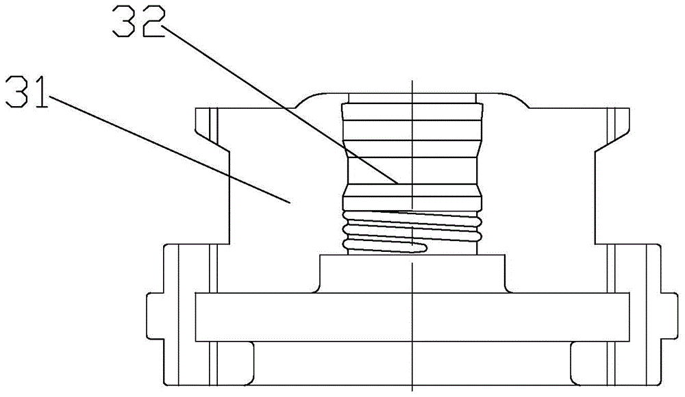
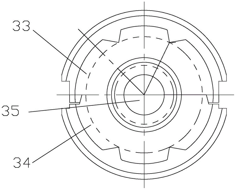
[0028] Embodiment: a kind of die that can exhaust, as image 3 , Figure 4 and Figure 5 As shown, the die 3 is made up of a male mold 33 and a female mold 34 that cooperate with each other. On the plane part 31 of the male mold 33 and the female mold 34, a cavity 32 that penetrates up and down is provided. The two cavity 32 Cooperate with each other so that a bottle cavity 35 is formed inside the entire mouth die 3. The surface that the male die 33 and the female die 34 are fitted together is called the seam surface 36, and the seam surface 36 is along the shape of the mold. The outer edges on both sides of the cavity 32 are set and protrude from the plane part 31, and each joint surface 36 is provided with a longitudinally arranged air guide groove 361, and the joint surface 36 on both sides of each air guide groove 361 There is also a laterally arranged exhaust groove A362 on the part, and the air guide groove 361 communicates with the inside of the bottle mouth 35 and th...


PUM

PropertyMeasurementUnit
lengthaaaaaaaaaa
depthaaaaaaaaaa
lengthaaaaaaaaaa

Abstract

The invention relates to a neck mould capable of exhausting. The neck mould consists of a male mould and a female mould. Joint surfaces on the male neck mould and the female neck mould are arranged along exteriors of the two sides of a moulding cavity and are protruded from a plane portion. A gas guiding groove is vertically arranged on each joint surface. A plurality of transversally-arranged exhausting grooves A are disposed on joint surface portions on the two sides of each gas guiding groove. The gas guiding groove communicates an interior of a bottle neck cavity with external air through the exhausting groove A. A plurality of exhausting grooves B are arranged on an upper end surface of the neck mould and enables the interior of the bottle neck cavity to be communicated with the external air. Compared with a neck mould in the prior art, phenomena that a bottle neck is not round in shape and material jump and material deviation of a glass material can be avoided through arrangement of the gas guiding groove and the exhausting grooves A on the joint surfaces and arrangement of the plurality of exhausting grooves B on the upper end surface so that production quality and production efficiency of glass bottles are increased. Meanwhile, by means of arrangement of the joint surfaces, a match area of joint surfaces and a match tolerance in the prior art are reduced. The joint surfaces are manufactured in a manner of being protruded from the plane portion so that a clearance is provided for enabling gas to be exhausted to the exterior through the exhausting groove A.

Description

technical field [0001] The invention relates to glass bottle blank processing accessories, in particular to a venting die. Background technique [0002] Such as figure 1 As shown, in the manufacturing process of glass bottles, it is necessary to pass the melted glass frit 1 through the cooperation of the blank mold 2, the mouth mold 3, the mouth ring 4, the core (not shown) and the bulkhead (not shown). The glass bottle is preliminarily formed. Among them, the mouth mold 3 is used to form the glass bottle mouth, mainly forming the overall shape, size, bottle mouth thread, etc. of the bottle mouth. It is one of the important molds for manufacturing glass bottles. Specifically, as figure 2 and image 3 As shown, the mouth die 3 is formed by the cooperation of the male die 33 and the female die 34, and the die cavity 32 connecting up and down is provided on the plane part 31 of the male die 33 and the female die 34, and the two die cavities 32 are connected to each other. ...

Claims


Application Information

Patent Timeline
Patent Type & Authority Patents(China)
IPC IPC(8): C03B9/325
CPCY02P40/57
Inventor 陈向明
Owner DEQING CAIFU GLASS
Why Eureka
Try Eureka