Fuel manifold for engine combustor and manufacturing method and aeroengine
A fuel manifold and combustion chamber technology, applied in the field of aero-engines, can solve the problems of explosion, processing, difficult control of welding quality, oil leakage, etc., to achieve the effect of less risk of oil leakage, meeting power requirements, and simple installation
- Summary
- Abstract
- Description
- Claims
- Application Information
AI Technical Summary
Problems solved by technology
Method used
Image
Examples
Embodiment Construction
[0026] The embodiments of the present invention will be described in detail below with reference to the accompanying drawings, but the present invention can be implemented in various ways defined and covered.
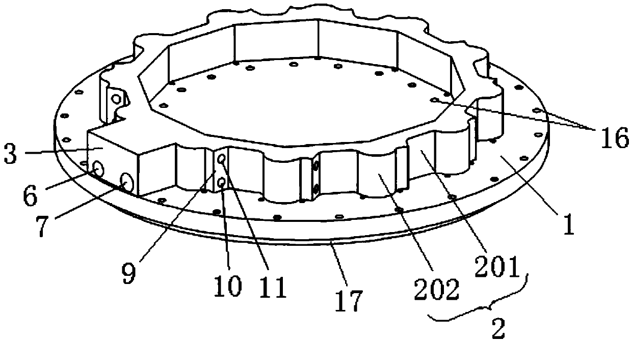
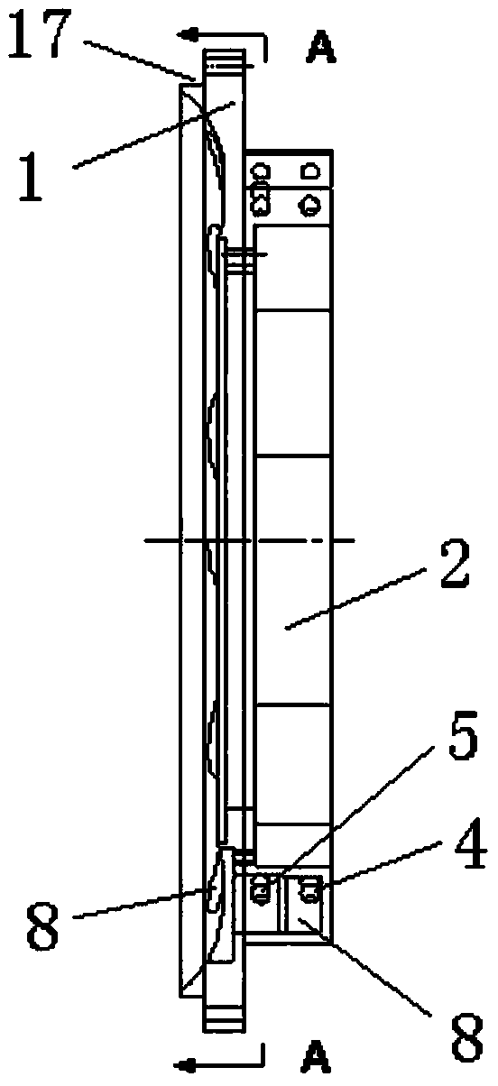
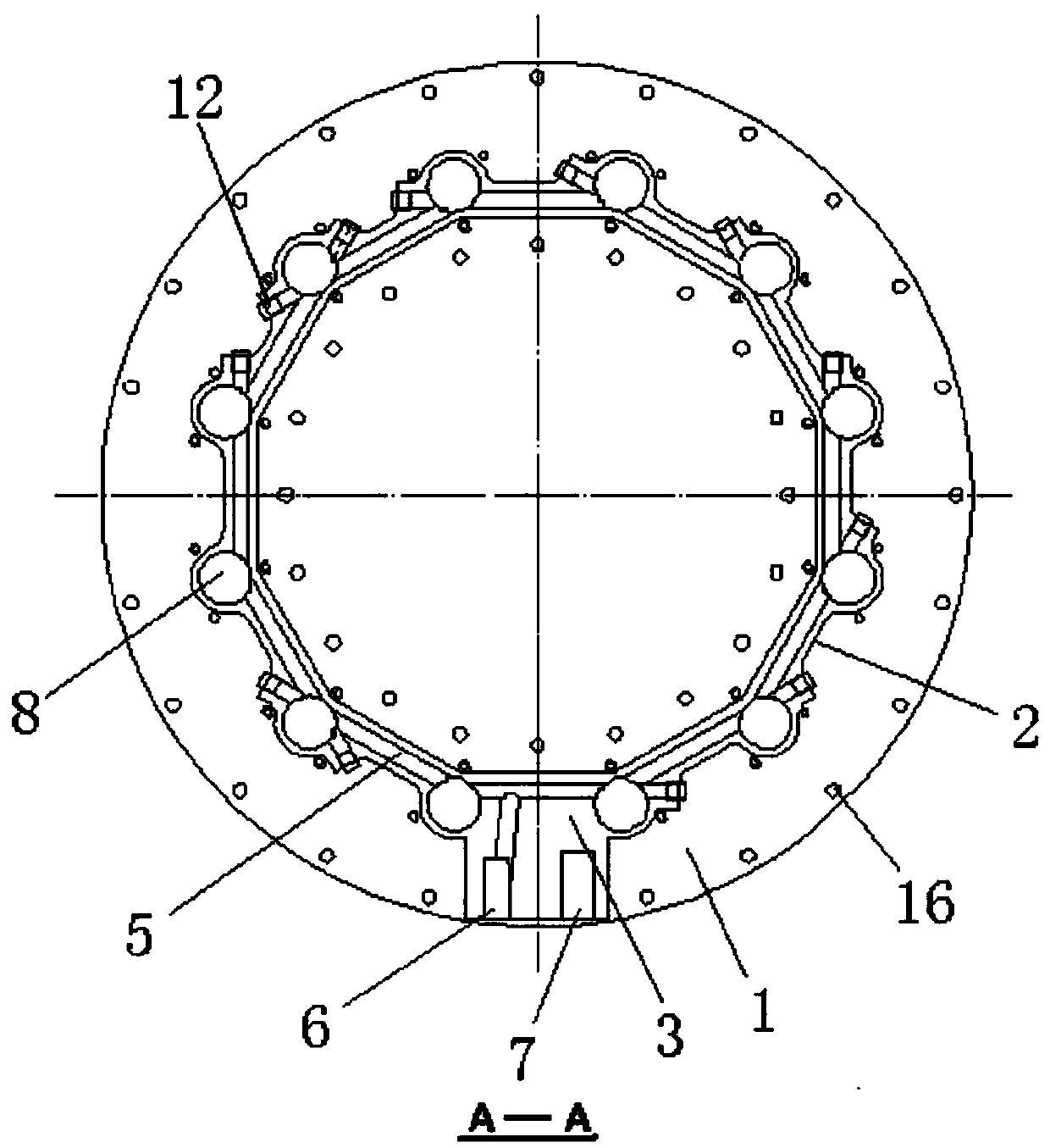
[0027] figure 1 It is one of the structural schematic diagrams of the fuel manifold used in the combustion chamber of the engine according to the preferred embodiment of the present invention; figure 2 It is the second structural schematic diagram of the fuel manifold used in the combustion chamber of the engine according to the preferred embodiment of the present invention; image 3 yes figure 1 Middle A-A sectional view; Figure 4 It is a schematic diagram of the assembly structure of the fuel manifold and the combustion chamber used in the combustion chamber of the engine according to the preferred embodiment of the present invention.
[0028] Such as figure 1 As shown, the fuel main pipe for the engine combustion chamber of the present embodiment includes an...
PUM
 Abstract
Description
Claims
Application Information
 - R&D
- Intellectual Property
- Life Sciences
- Materials
- Tech Scout
- Unparalleled Data Quality
- Higher Quality Content
- 60% Fewer Hallucinations
Browse by: Latest US Patents, China's latest patents, Technical Efficacy Thesaurus, Application Domain, Technology Topic, Popular Technical Reports.
© 2025 PatSnap. All rights reserved.Legal|Privacy policy|Modern Slavery Act Transparency Statement|Sitemap|About US| Contact US: help@patsnap.com


