Method for rapidly obtaining constant gas humidity

A gas and humidity technology, applied in the field of gas humidity generation, can solve the problems of complex operation and narrow humidity generation range, and achieve the effects of simple operation, high accuracy and wide generation range

Inactive Publication Date: 2014-11-19
STATE GRID CORP OF CHINA +1
View PDF8 Cites 10 Cited by
  • Summary
  • Abstract
  • Description
  • Claims
  • Application Information

AI Technical Summary

Problems solved by technology

[0004] The purpose of the present invention is to solve the problems of the existing method for obtaining constant humidity, the range of the o

Method used


Image

  • Method for rapidly obtaining constant gas humidity

Examples


specific Embodiment approach 1

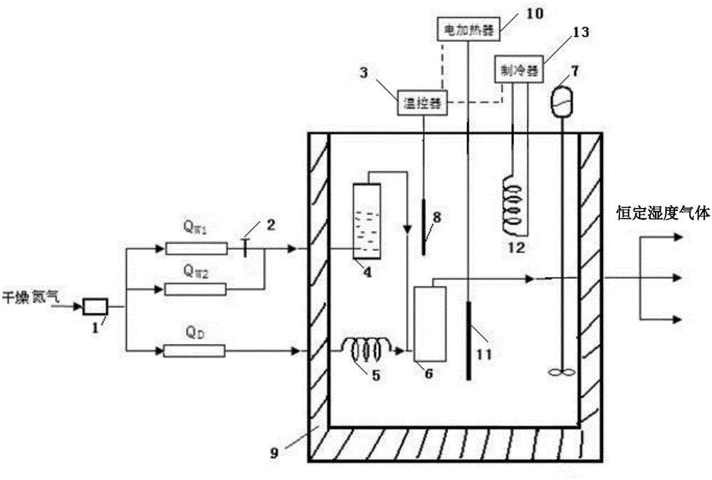
[0016] Specific implementation mode one: see figure 1 Describe this embodiment, a method for quickly obtaining constant gas humidity described in this embodiment, the method is realized based on a humidity generating device, the device includes a pressure controller 1, a mass flow controller Q1 w1 , No. 2 mass flow controller Q w2 , No. 3 mass flow controller Q D , temperature controller 3, saturator 4, No. 1 heat exchange tube 5, mixing chamber 6, electric stirrer 7, temperature sensor 8, constant temperature water bath box 9, electric heater 10, electric heating rod 11, refrigeration heat exchange tube 12 and refrigerator 13;

[0017] The pressure controller 1 is used to simultaneously press the gas source into the No. 1 mass flow controller Q w1 , No. 2 mass flow controller Q w2 and No. 3 mass flow controller Q D , and No. 1 mass flow controller Q w1 and No. 2 mass flow controller Q w2 The gas outlet of the saturator is connected with the saturator 4 at the same time...

specific Embodiment approach 2

[0033] Embodiment 2: The difference between this embodiment and the method for quickly obtaining constant gas humidity described in Embodiment 1 is that a humidity generating device also includes a shut-off valve 2, and the shut-off valve 2 is set at No. 1 mass flow rate Controller Q w1 at the air outlet.

[0034] In this embodiment, in order to prevent No. 1 mass flow controller Q w1 Air leakage affects No. 2 mass flow controller Q w2 For the control of gas flow, install stop valve 2 to cut off the road.

specific Embodiment approach 3

[0035] Embodiment 3: The difference between this embodiment and the method for quickly obtaining a constant gas humidity described in Embodiment 1 is that the inner wall of the constant temperature water bath box 9 is provided with an insulating layer.

[0036] In this embodiment, the heat insulation layer better maintains the temperature of the constant temperature water bath in the constant temperature water bath box 9 .


PUM

PropertyMeasurementUnit
Thicknessaaaaaaaaaa

Abstract

The invention relates to a method for rapidly obtaining constant gas humidity, which belongs to the gas humidity generation field. The method solves the problems of narrow obtained humidity generation scope and complex operation in the current constant humidity obtaining methods. The method is characterized in that an electric heater and a refrigerator are used for real time control of water-bath temperature in a constant temperature water-bath box, water-bath temperature in the constant temperature water-bath box is constant; after the water-bath temperature in the constant temperature water-bath box is constant, a pressure controller is used for drying nitrogen and pressing into No1-No3 mass flow controllers, drying nitrogen through the No1-No2 mass flow controllers pass through a saturator and then is introduced in a mixing chamber, the drying nitrogen through the No3 mass flow controller is introduced in a mixing chamber through a No1 heat exchange tube, constant humidity gas is output from the mixing chamber, so that constant gas humidity can be obtained. The method is used for obtaining the constant gas humidity.

Description

technical field [0001] The invention belongs to the field of gas humidity generation. Background technique [0002] Sulfur hexafluoride and its mixed gas have excellent insulation and arc extinguishing properties, and are the main insulating medium for high-voltage electrical equipment, and the humidity of the gas determines the quality of its insulation performance. Therefore, new sulfur hexafluoride and operating conditions should be monitored during production and operation Humidity of sulfur hexafluoride gas in electrical equipment. Instruments used for gas humidity measurement are generally divided into electrolytic hygrometers, resistance-capacitance hygrometers and dew point meters according to their detection principles. Instruments with different detection principles, instruments produced by different manufacturers with the same principle, and the same instrument at different stages in the use process may cause deviations in the detection results due to changes in ...

Claims


Application Information

Patent Timeline
IPC IPC(8): G01N33/00
Inventor 李国兴姜子秋王晓丹
Owner STATE GRID CORP OF CHINA
Why Eureka
Try Eureka