Eureka AIR delivers breakthrough ideas for toughest innovation challenges, trusted by R&D personnel around the world.

Voltage regulating apparatus

a voltage regulating apparatus and voltage technology, applied in the direction of electric variable regulation, process and machine control, instruments, etc., can solve the problems of a very long settling time and large current consumption in the band-gap circuit itself, so as to reduce unnecessary current consumption and reduce the settling time

Inactive Publication Date: 2007-11-29
SAMSUNG ELECTRO MECHANICS CO LTD
View PDF5 Cites 9 Cited by
  • Summary
  • Abstract
  • Description
  • Claims
  • Application Information

AI Technical Summary

Benefits of technology

[0011]An aspect of the present invention provides a voltage regulating apparatus with a short settling time and a small current consumption.
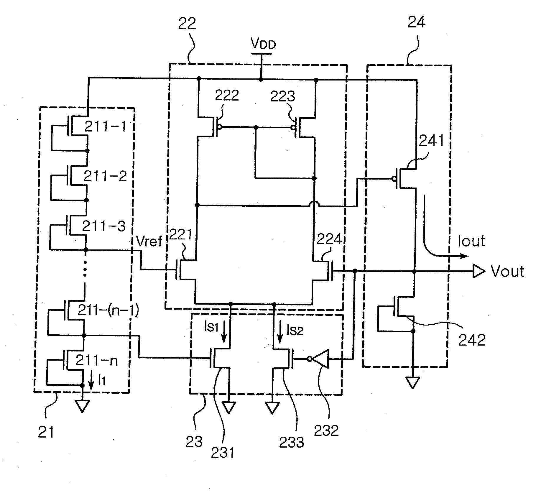
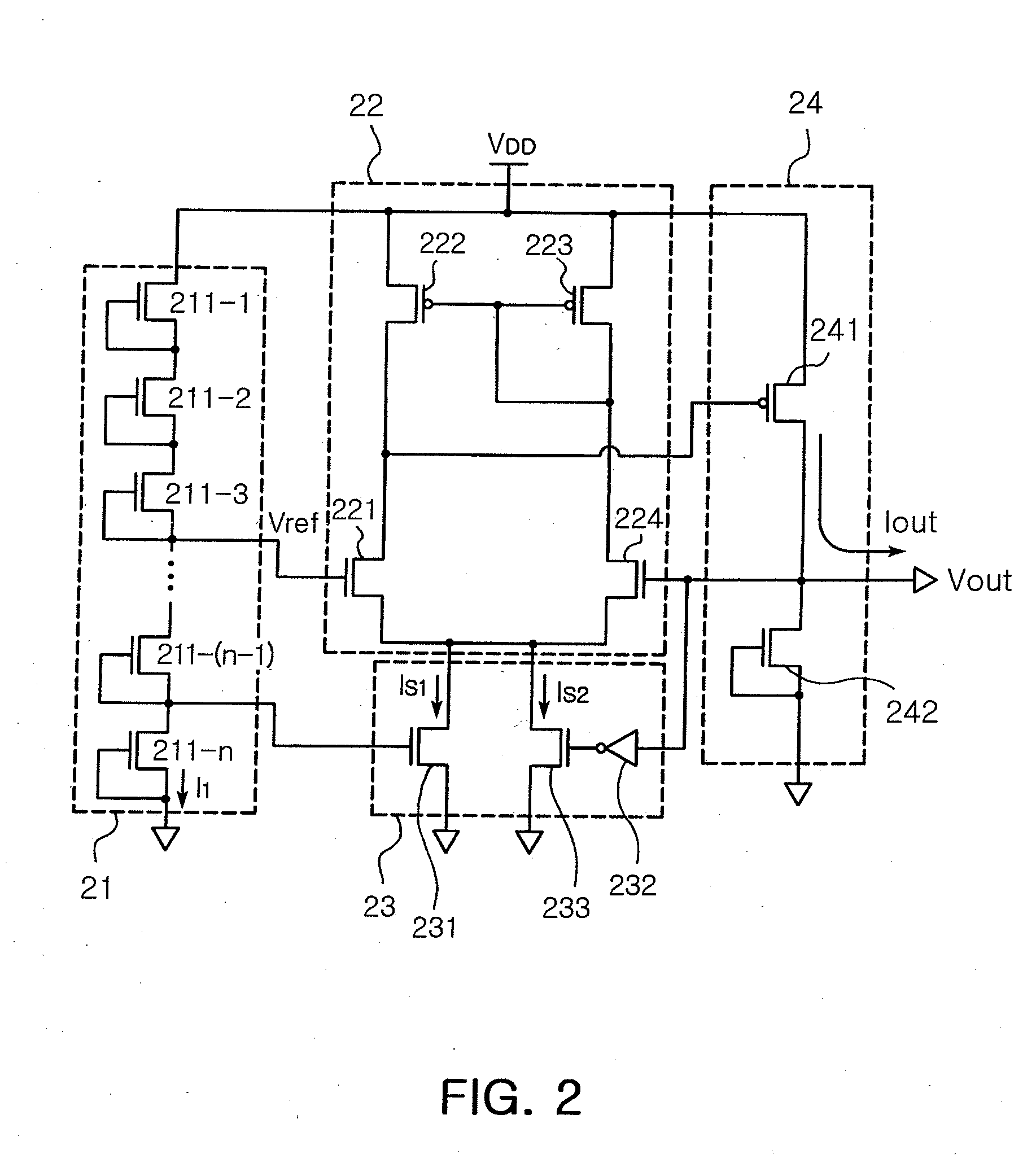
[0018]The second current sink may include: an inverter connected to the gate of the fourth MOSFET and inverting the voltage of the gate of the fourth MOSFET; and an MOSFET having a drain connected to the sources of the first MOSFET and the fourth MOSFET, a source grounded, and a gate to which the inverted voltage is applied. The second current sink may be applied to reduce a settling time for outputting an output voltage identical with the reference voltage when the apparatus initially operates.
[0019]The voltage comparator may further include a plurality of MOSFETs having a drain connected to the drain of the first MOSFET, a source connected to the drain of the fourth MOSFET, and a gate to which the supply voltage is applied. The plurality of MOSFETs connected between the first MOSFET and the fourth MOSFET may operate as resistors to prevent an excessive voltage increase capable of occurring during the settling time.
[0020]The voltage output unit may further include an MOSFET having a drain connected to the gate of the fourth MOSFET and a gate and a source grounded, thereby having an approximately infinite resistance value. An unnecessary current consumption may be reduced by applying the MOSFET having the infinite resistance value.

Problems solved by technology

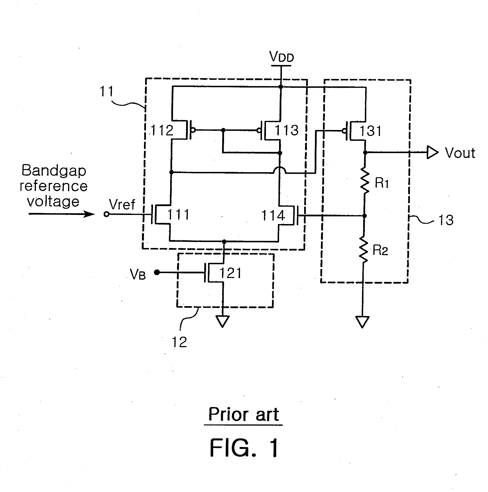
There is a problem of a large current consumption in the band-gap circuit itself.
Also, since the conventional voltage regulating apparatus provides the sink current via one MOSFET 121, there is a problem of a very long settling time for regulating the output voltage to be identical with the reference voltage Vref in an apparatus requiring a small current consumption.

Method used


Image

  • Voltage regulating apparatus
  • Voltage regulating apparatus
  • Voltage regulating apparatus

Examples


Embodiment Construction

[0025]Hereinafter, the present invention will now be described more fully with reference to the accompanying drawings, in which exemplary embodiments of the invention are shown. The present invention may, however, be embodied in many different forms and should not be construed as being limited to the embodiments set forth herein; rather, these embodiments are provided so that this disclosure will be thorough and complete, and will fully convey the concept of the invention to those skilled in the art. In the drawings, the thicknesses of layers and regions are exaggerated for clarity. Like reference numerals in the drawings denote like elements, and thus their description will be omitted.

[0026]FIGS. 2 and 3 are circuit diagrams illustrating voltage regulating apparatuses according to two embodiments of the present invention, respectively.

[0027]Referring to FIG. 2, the voltage regulating apparatus according to an embodiment of the present invention includes a reference voltage generato...


PUM


Abstract

There is disclosed a voltage regulating apparatus with a short settling time and a small current consumption. The voltage regulating apparatus comprises a reference voltage generator including an MOSFET array comprising a plurality of MOSFETs with a structure in which a drain and a source are connected in series with each other, a supply voltage is applied to the drain of the MOSFET located in an end of the MOSFET array and the source of the MOSFET located in another end is grounded, and the reference voltage is a voltage obtained by dividing by the plurality of MOSFETs of the MOSFET array at a predetermined ratio.

Description

CROSS-REFERENCE TO RELATED APPLICATIONS[0001]This application claims the priority of Korean Patent Application No. 2006-0047723 filed on May 26, 2006, in the Korean Intellectual Property Office, the disclosure of which is incorporated herein by reference.BACKGROUND OF THE INVENTION[0002]1. Field of the Invention[0003]The present invention relates to a voltage regulating apparatus, and more particularly, to a voltage regulating apparatus capable of reducing current consumption and reducing an amount of time used until stably operating when regulating a supply voltage provided from a power supply into a voltage required for operating a semiconductor device.[0004]2. Description of the Related Art[0005]In general, semiconductor devices operate by receiving a driving voltage provided by an external power supply. Since a size of the voltage provided from the power supply is fixed, to drive semiconductor devices operating by a voltage with a different size from the output voltage of the po...

Claims


Application Information

Patent Timeline
Patent Type & Authority Applications(United States)
IPC IPC(8): H01L29/76
CPCG05F1/46H02M1/08
Inventor KWON, YONG ILLIM, JOON HYUNGPARK, TAH JOON
Owner SAMSUNG ELECTRO MECHANICS CO LTD
Why Eureka
Eureka Blog
Learn More