Switched combining antenna diversity technique

a technology of switching and antenna diversity, applied in diversity/multi-antenna systems, wireless communication, wireless communication, etc., can solve the problems of increasing the complexity of each branch's signal-to-interference ratio, and increasing the complexity of each branch's signal. , to achieve the effect of improving antenna diversity, low complexity and high performan

Active Publication Date: 2008-04-29
GLOBALFOUNDRIES US INC
View PDF18 Cites 9 Cited by
  • Summary
  • Abstract
  • Description
  • Claims
  • Application Information

AI Technical Summary

Benefits of technology

[0013]A method of selecting one of at least two antennae of a communication device and a corresponding communication device and wireless LAN receiver are disclosed that may provide an improved antenna diversity having low complexity, high performance and short settling time.

Problems solved by technology

This signal variation can lead to situations, where a receiver with a single antenna cannot receive a sufficiently strong signal to achieve acceptable performance.
However, due to the fact that systems cannot receive signals from different antennae at the same time, the internal time constants have to be considerably shorter than the fading periods for the system to operate efficiently.
Moreover, the measurement of each branch's signal-to-interference ratio is associated with an enhanced system complexity.
While a maximal ratio combining array can achieve optimal performance in the presence of noise, it does not provide the ability to reject interference.
These antenna diversity techniques are disadvantageous since they need separate receivers REC, each including a radio frequency and base band part, in each branch.
This is a requirement that leads to considerably high system costs.
However, existing switched combining systems may take an unacceptably long time for detecting when the signal-to-noise ratio drops below the acceptable threshold.
This reduces the time available for synchronization, equalization etc. and may therefore reduce the signal quality or even lead to data loss.

Method used


Image

  • Switched combining antenna diversity technique
  • Switched combining antenna diversity technique
  • Switched combining antenna diversity technique

Examples


Embodiment Construction

[0028]The illustrated embodiments of the present invention will be described with reference to the figure drawings wherein like elements and structures are indicated by like reference numbers.

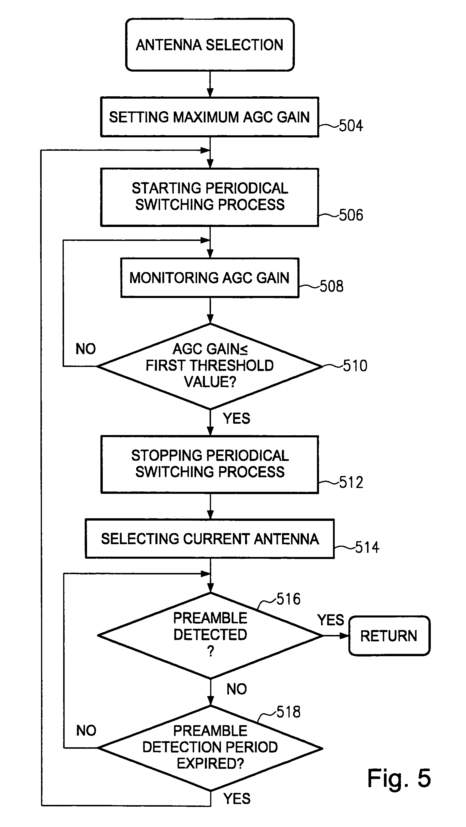
[0029]Referring now to the drawings and in particular to FIG. 5 which is a flowchart of an antenna diversity method of selecting one of at least two antennae of a communication device, the process shown therein enables a communication device to select an adequate antenna within a time that is preferably shorter than the length of a preamble within a signal frame. Preambles will now be described with reference to FIG. 6.

[0030]As shown in FIG. 6, wherein a timing diagram of a data communication encoding format is shown, each signal frame 608 begins with a preamble 602 that comprises a bit pattern which may have a duration of e.g. 72 microseconds for a short preamble or 144 microseconds for a long preamble. The preamble 602 may comprise a sync field of 56 or 128 microseconds, respectively, and a 1...


PUM


Abstract

An antenna diversity method and a corresponding communication device are disclosed that may be used in wireless LAN receivers. An AGC (Automatic Gain Control) unit controls a gain when processing signals received from antennae. A periodical switching process is performed between at least two antennae. During this periodical switching process, signals from each of the antennae are received alternately. The gain obtained by processing each received signal by means of the AGC unit is monitored and the obtained gain is compared with a predetermined threshold value. When for one of the at least two antennae the gain is below the predetermined threshold value, the periodical switching process is stopped and the antenna used at the time when stopping the periodical switching process is selected. This technique may provide an improved antenna diversity of low complexity, high performance and a short settling time.

Description

BACKGROUND OF THE INVENTION[0001]1. Field of the Invention[0002]The invention generally relates to communication devices and methods, and more specifically to switched combining antenna diversity techniques particularly in wireless LAN (Local Area Networks, WLAN) systems.[0003]2. Description of the Related Art[0004]In a mobile radio channel, the signal level received at an antenna depends strongly on the location of the reception point. There can be large variations in the signal level over rather short distances. This signal variation can lead to situations, where a receiver with a single antenna cannot receive a sufficiently strong signal to achieve acceptable performance. On the other hand, if more than one antenna is used, the chance that at least one antenna receives a sufficiently strong signal is increased. The approach of using several antennae that are spaced apart is called space or antenna diversity. Presently, several techniques for performing antenna diversity in a wire...

Claims


Application Information

Patent Timeline
Patent Type & Authority Patents(United States)
IPC IPC(8): H04Q7/00H04B7/08
CPCH04B7/0822
Inventor POEGEL, FRANKKLUGE, WOLFRAMSACHSE, ERIC
Owner GLOBALFOUNDRIES US INC
Why Eureka
Try Eureka