Protection device and protection method for cable sheath in power construction process

A protection device and electric power construction technology, which is applied in the direction of cable installation device, cable installation, electrical components, etc., can solve the problems of easy twisting of wires, easy twisting and entanglement, time-consuming and labor-intensive movement and recycling, etc., to achieve convenience Move or recycle, easy to release torsion force, drag and save time and effort

Inactive Publication Date: 2014-11-19
NANYANG POWER SUPPLY COMPANY OF STATE GRID HENAN ELECTRIC POWER
View PDF7 Cites 16 Cited by
  • Summary
  • Abstract
  • Description
  • Claims
  • Application Information

AI Technical Summary

Problems solved by technology

Especially in the process of phase change (the equipment under test is changed from phase A to phase B or phase C), the wires are easy to be twisted and entangled on the ground, and the wires are also easy to twist and damage the wires. And recycling takes time and labor, and the cable itself is long and heavy, so it is very inconvenient to move. The usual method is to put the cable that needs to be moved on the ground, and then twist the cable by multiple people by dragging it. It is moving to the new equipment under test. In this case, the outer skin of the cable is in frequent contact with the sharp corners of sand and gravel, which is easy to be scratched. In addition, the construction site environment is relatively harsh, and the equipment leaks on the ground during the installation and commissioning process. If the oil-water mixture on the surface is not cleaned up in time, the sheath of the cable will be corroded after contact with the sheath of the cable. The cable after the sheath is scratched or corroded is damaged due to insulation, and the insulation capacity is reduced, which directly affects the performance of the test equipment. The test effect of the equipment will lead to safety accidents in severe cases, resulting in damage to the test equipment or the equipment under test, as well as personal injury and death accidents, with disastrous consequences

Method used


Image

  • Protection device and protection method for cable sheath in power construction process
  • Protection device and protection method for cable sheath in power construction process
  • Protection device and protection method for cable sheath in power construction process

Examples


Embodiment 1

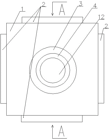
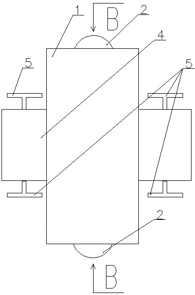
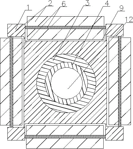
[0031] Embodiment 1: as figure 1 , 2 , 3, 4, 5, and 7, a cable sheath protection device in the electric power construction process, including a housing 1, the upper end of the housing 1 is provided with at least one rolling mechanism, and the housing 1 is provided with A through hole 12 perpendicular to the axial direction of the rotating shaft 6 of the rolling mechanism, the through hole 12 is provided with a bearing 3, and the inner tube 4 is sleeved in the bearing 3, and the two ends of the inner tube 4 protrude from the through hole, so Both ends of the inner tube 4 are provided with wire adjustment and fixing mechanisms.

[0032] The rolling mechanism includes a groove 9 and a rotating shaft 6 arranged on the upper end of the housing, the rotating shaft 6 is located on the upper part of the groove 9 so that a part of the roller 2 sleeved on the rotating shaft is located outside the groove 9 .

[0033] A bearing 3 is inlaid in the through hole 12 , and the bearing 3 is ...

Embodiment 2

[0045] Embodiment 2: as figure 1 As shown, a cable sheath protection device in the electric power construction process includes a housing 1, the upper end of the housing 1 is provided with at least one rolling mechanism, and the housing 1 is provided with a rotating shaft 6 axial to the rolling mechanism. Perpendicular to the through hole 12, the bearing 3 is arranged in the said through hole 12, the inner tube 4 is sleeved in the bearing 3, the two ends of the inner tube 4 protrude from the through hole, and the two ends of the inner tube 4 are provided with Wire adjustment fixing mechanism.

[0046] A bearing 3 is inlaid in the through hole 12 , and the bearing 3 is sleeved on the inner tube 4 so that the inner tube 4 is connected to the housing 1 in rotation.

[0047] The wire adjustment and fixing mechanism includes two clamping mechanisms symmetrically arranged at the end of the inner tube 4, and the clamping mechanism includes a screw rod 5 and an arc-shaped claw 8 th...

Embodiment 3

[0059] Embodiment 3: as figure 1 As shown, a cable sheath protection device in the electric power construction process includes a housing 1, the upper end of the housing 1 is provided with at least one rolling mechanism, and the housing 1 is provided with a rotating shaft 6 axial to the rolling mechanism. Perpendicular to the through hole 12, the bearing 3 is arranged in the said through hole 12, the inner tube 4 is sleeved in the bearing 3, the two ends of the inner tube 4 protrude from the through hole, and the two ends of the inner tube 4 are provided with Wire adjustment fixing mechanism.

[0060] The rolling mechanism includes a groove 9 arranged on the upper end of the housing and a rotating shaft 6 , the rotating shaft 6 is located on the upper part of the groove 9 so that a part of the roller 2 sleeved on the rotating shaft is located outside the groove 9 .

[0061] A bearing 3 is inlaid in the through hole 12 , and the bearing 3 is sleeved on the inner tube 4 so tha...


PUM


Abstract

The invention discloses a protection device for a cable sheath in the power construction process. The protection device comprises a shell, wherein one or more rolling mechanisms are arranged at the upper end of the shell; a through hole axially perpendicular to a rotating shaft of each rolling mechanism is formed in the shell; a bearing is arranged in the through hole; an inner pipe is sleeved by the bearing; two ends of the inner pipe stretch out of the through hole; a conducting wire adjusting and fixing mechanism is arranged at each of the two ends of the inner pipe. By the adoption of the bearing arranged inside the shell, the cable moves forwards under the action of a dragger, a conducting wire is easy to automatically rotate due to the dead weight per se, and a twisted conducting wire is loosened to greatly facilitate moving or recycling of the conducting wire without damaging the wire sheath.

Description

technical field [0001] The invention belongs to the technical field of electric power construction cable moving sheath protection equipment, and in particular relates to a cable sheath protection device and a protection method in the electric power construction process. Background technique [0002] At present, there are many kinds of various electric equipment test instruments used by the team, and each test instrument is equipped with different power lines, data lines and special lines for testing, etc. The diameters of these cables with different functions and specifications are relatively small. The thin ones are about 5mm, the thicker ones are about 40mm, the short ones are more than ten meters long, and the long ones are tens of meters long, or even hundreds of meters long. Big difference. [0003] Due to the high frequency of use of the test equipment, the ground of the substation site is not only the cement floor, but also the sandy and petrified ground. During the ...

Claims


Application Information

Patent Timeline
Patent Type & Authority Applications(China)
IPC IPC(8): H02G1/00
Inventor 时伟王飞李春晖
Owner NANYANG POWER SUPPLY COMPANY OF STATE GRID HENAN ELECTRIC POWER
Why Eureka
Try Eureka