Inductance determination method and device for permanent-magnet synchronous motor
A technology for permanent magnet synchronous motors and determination methods, which is applied in the direction of controlling electromechanical transmissions, controlling generators, motor generators, etc., and can solve problems such as poor detection accuracy
- Summary
- Abstract
- Description
- Claims
- Application Information
AI Technical Summary
Problems solved by technology
Method used
Image

Examples
Embodiment 1
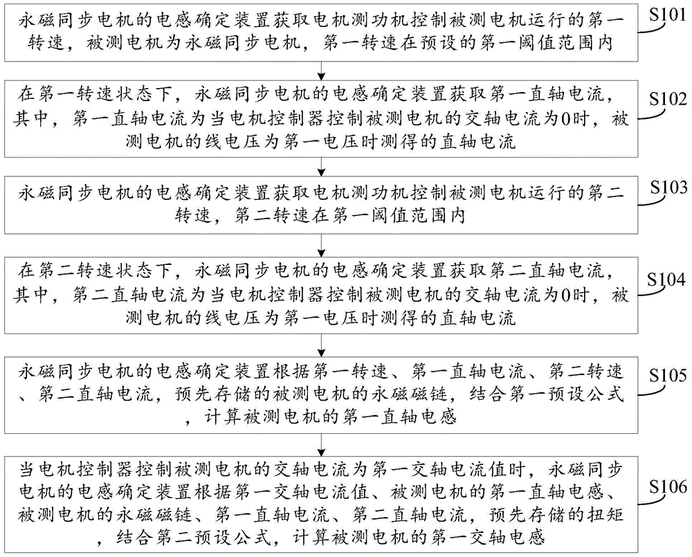
[0094] An embodiment of the present invention provides a method for determining the inductance of a permanent magnet synchronous motor, specifically as figure 1 shown, including:
[0095] S101. The device for determining the inductance of the permanent magnet synchronous motor obtains a first rotational speed at which the motor dynamometer controls the operation of the motor under test. The motor under test is a permanent magnet synchronous motor, and the first rotational speed is within a preset first threshold range.
[0096] It should be noted that, in the embodiment of the present invention, the left end point of the first threshold range should be set higher for the following reasons:
[0097] According to the voltage equation of permanent magnet synchronous motor shown in formula (1) and formula (2), when the measured motor speed ω is as high as possible, the last item in formula (1) and formula (2) is much greater than the other Two items, and then the other two items ...
Embodiment 2
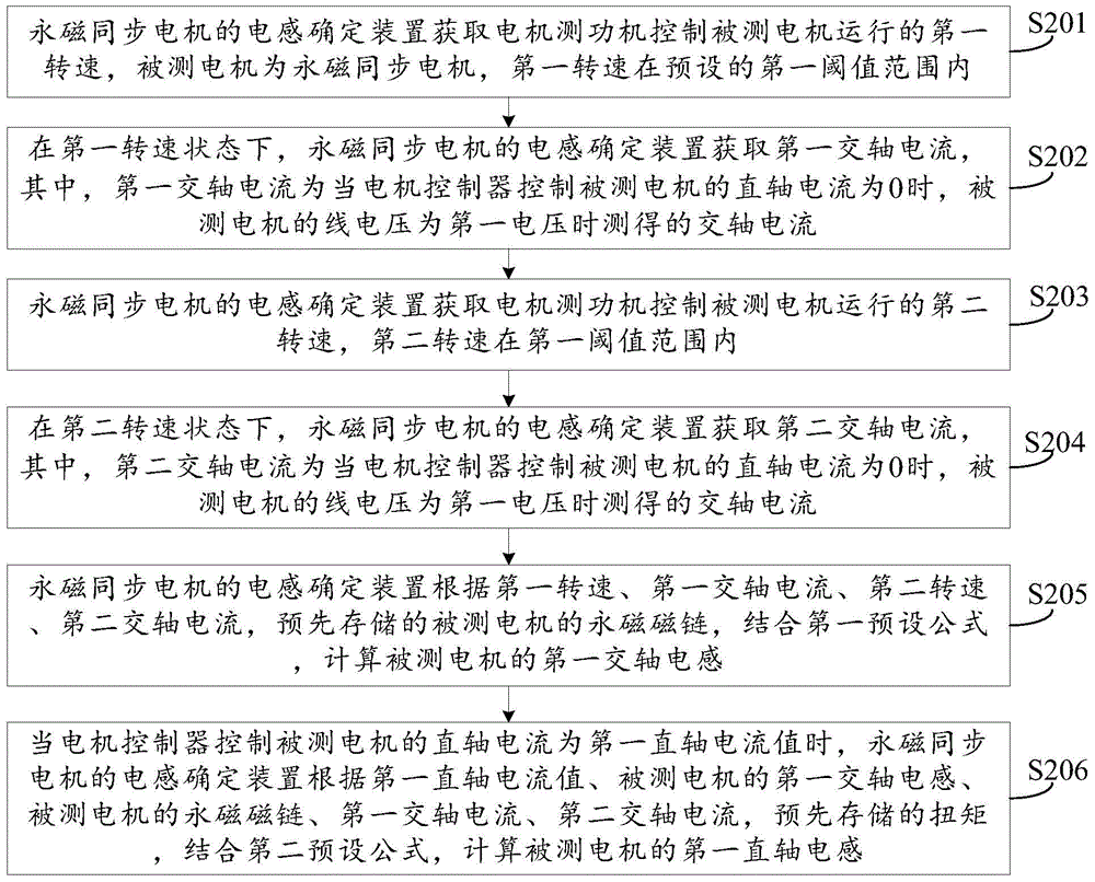
[0131] An embodiment of the present invention provides a method for determining the inductance of a permanent magnet synchronous motor, specifically as figure 2 shown, including:
[0132] S201. The device for determining the inductance of the permanent magnet synchronous motor acquires a first rotational speed at which the motor dynamometer controls the operation of the motor under test. The motor under test is a permanent magnet synchronous motor, and the first rotational speed is within a preset first threshold range.
[0133] It should be noted that, in the embodiment of the present invention, the left end point of the first threshold range should be set higher, and the specific reason may refer to the description of Embodiment 1, which will not be repeated in the embodiment of the present invention.
[0134] In order to ensure the normal operation of the motor under test, the speed of the motor under test should not be greater than the preset base speed of the motor under...
Embodiment 3
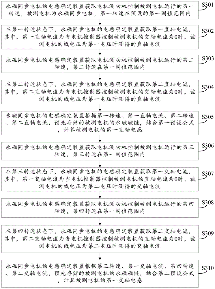
[0159] An embodiment of the present invention provides a method for determining the inductance of a permanent magnet synchronous motor, specifically as image 3 shown, including:
[0160] S301. The device for determining the inductance of the permanent magnet synchronous motor acquires a first rotational speed at which the motor dynamometer controls the operation of the motor under test. The motor under test is a permanent magnet synchronous motor, and the first rotational speed is within a preset first threshold range.
[0161]It should be noted that, in the embodiment of the present invention, the left end point of the first threshold range should be set higher, and the specific reason may refer to the description of Embodiment 1, which will not be repeated in the embodiment of the present invention.
[0162] In order to ensure the normal operation of the motor under test, the speed of the motor under test should not be greater than the preset base speed of the motor under t...
PUM
 Abstract
Description
Claims
Application Information
 - R&D
- Intellectual Property
- Life Sciences
- Materials
- Tech Scout
- Unparalleled Data Quality
- Higher Quality Content
- 60% Fewer Hallucinations
Browse by: Latest US Patents, China's latest patents, Technical Efficacy Thesaurus, Application Domain, Technology Topic, Popular Technical Reports.
© 2025 PatSnap. All rights reserved.Legal|Privacy policy|Modern Slavery Act Transparency Statement|Sitemap|About US| Contact US: help@patsnap.com