Two-stage sandwich type traveling wave piezoelectric centrifugal pump and driving method thereof

A sandwich type, traveling wave technology, used in non-variable-capacity pumps, non-displacement pumps, pumps, etc., can solve the problems of electromagnetic pollution of the motor, large size and difficult miniaturization, and large noise, and achieve the effect of easy integration and installation.

Pending Publication Date: 2019-11-08
NANJING UNIV OF AERONAUTICS & ASTRONAUTICS
View PDF0 Cites 0 Cited by
  • Summary
  • Abstract
  • Description
  • Claims
  • Application Information

AI Technical Summary

Problems solved by technology

[0002] When the traditional centrifugal pump works, it needs to be driven by an external motor. In this way, the motor and the centrifugal pump are separated, so the structure is complex, and the volume is large and it is not easy to miniaturize; moreover, the fluid control accuracy of the centrifugal pump is not high, and it cannot supply small flow. It will generate a lot of noise; in addition, the operation of traditional motors will generate electromagnetic pollution, which will limit its direct application in fields sensitive to magnetic fields such as medical care and hygiene
[0003] Conventional piezoelectric pumps use the inverse piezoelectric effect of piezoelectric materials to deform the piezoelectric sheet to change the volume of the pump cavity and realize liquid transmission. There are problems such as low output pressure and low output flow, which make its applicable range The reception is greatly limited, so increasing the output flow and output fluid pressure of the piezoelectric pump is a difficult problem for the current piezoelectric pump

Method used


Image

  • Two-stage sandwich type traveling wave piezoelectric centrifugal pump and driving method thereof
  • Two-stage sandwich type traveling wave piezoelectric centrifugal pump and driving method thereof
  • Two-stage sandwich type traveling wave piezoelectric centrifugal pump and driving method thereof

Examples


Embodiment Construction

[0050] Below in conjunction with accompanying drawing, technical scheme of the present invention is described in further detail:

[0051] This invention may be embodied in many different forms and should not be construed as limited to the embodiments set forth herein. Rather, these embodiments are provided so that this disclosure will be thorough and complete, and will fully convey the scope of the invention to those skilled in the art. In the drawings, components are exaggerated for clarity.

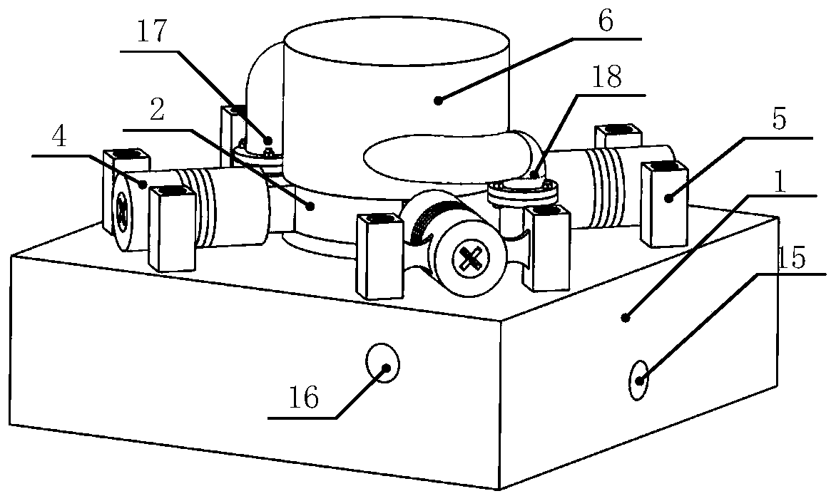
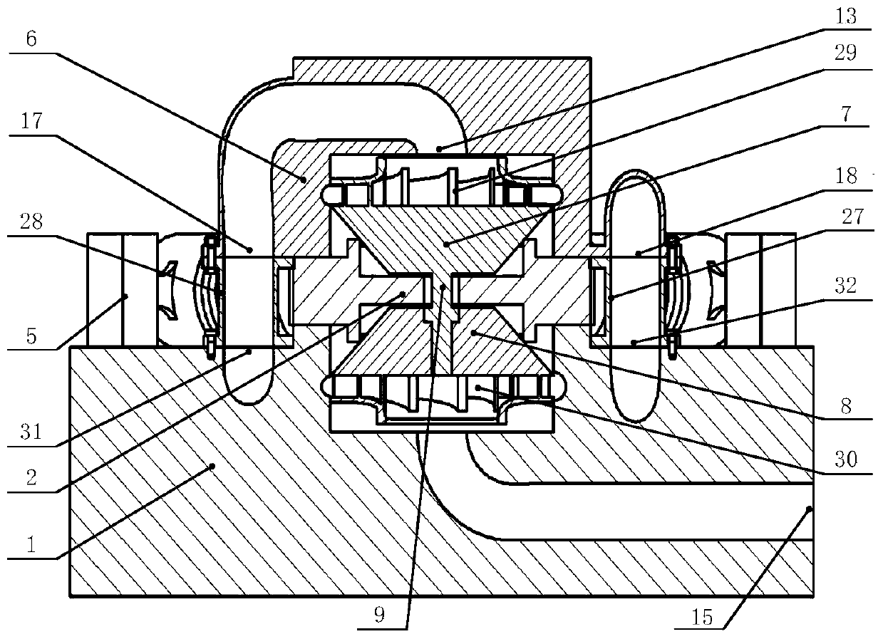
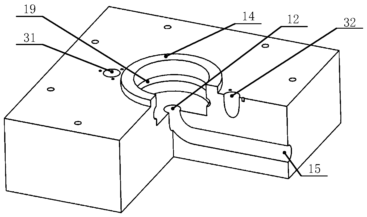
[0052] Such as figure 1 , figure 2 , image 3 As shown, the present invention discloses a two-stage sandwich traveling wave piezoelectric centrifugal pump, which includes a base, a stator, a casing, an upper rotor, a lower rotor, a connecting shaft, a positive closed impeller, a reverse closed impeller, a first connecting pipe fittings, second connecting pipe fittings and four piezoelectric ceramic modules;

[0053] The base is a cuboid, the center of its upper end surface is prov...


PUM


Abstract

The invention discloses a two-stage sandwich type traveling wave piezoelectric centrifugal pump and a driving method thereof. The two-stage sandwich type traveling wave piezoelectric centrifugal pumpcomprises a base, a stator, a shell, an upper rotor, a lower rotor, a connecting shaft, a forward-closed impeller, a reverse-closed impeller, a first connecting pipe fitting, a second connecting pipefitting and four piezoelectric ceramic modules. During work, the four piezoelectric ceramic modules are excited to drive a particle on the inner side of annular teeth to perform micro-amplitude elliptical motion, the upper rotor and the lower rotor are driven to further drive positive and negative closed impellers to rotate in the same direction, fluid obtains energy for the first time through thelower closed impeller, and then enters the upper closed impeller through a pipeline to obtain energy for the second time, so that the fluid is pressurized twice. The bending type contraposition laminating suction device is simple and compact in structure, easy to seal and miniaturize, capable of accurately controlling flow, fast in response, low in noise, free of electromagnetic interference andelectromagnetic interference, and capable of powering off and self-locking; and compared with a conventional piezoelectric pump, the piezoelectric pump has the advantages of large flow and large output fluid pressure.

Description

technical field [0001] The invention relates to the field of fluid machinery, in particular to a two-stage sandwich traveling wave piezoelectric centrifugal pump and a driving method thereof. Background technique [0002] When the traditional centrifugal pump works, it needs to be driven by an external motor. In this way, the motor and the centrifugal pump are separated, so the structure is complex, and the volume is large and it is not easy to miniaturize; moreover, the fluid control accuracy of the centrifugal pump is not high, and it cannot supply small flow. It will generate a lot of noise; in addition, the operation of traditional motors will generate electromagnetic pollution, which will limit its direct application in fields sensitive to magnetic fields such as medical treatment and hygiene. [0003] Conventional piezoelectric pumps use the inverse piezoelectric effect of piezoelectric materials to deform the piezoelectric sheet to change the volume of the pump cavity...

Claims


Application Information

Patent Timeline
Patent Type & Authority Applications(China)
IPC IPC(8): F04D13/06F04D1/06F04D29/22
CPCF04D1/06F04D13/06F04D29/2216
Inventor 尹永康王亮金家楣王方一刘瑞
Owner NANJING UNIV OF AERONAUTICS & ASTRONAUTICS
Why Eureka
Try Eureka