A Control Method of Panel and Lamp Based on Closed Carrier Technology

A closed carrier and control method technology, applied in the direction of lamp circuit layout, lighting devices, light sources, etc., can solve problems such as crosstalk, complex matching operations, increased construction difficulty and cost, and achieve simplified operation methods, flexible control methods, and communication methods various effects

Active Publication Date: 2017-01-04
厦门市致创能源技术有限公司
View PDF6 Cites 0 Cited by
  • Summary
  • Abstract
  • Description
  • Claims
  • Application Information

AI Technical Summary

Problems solved by technology

[0003] The above methods have their own characteristics, but there are also obvious problems: 1. The thyristor method is used. Due to the characteristics of the thyristor itself, its reliability is not high, and it can only realize one-way dimming without lamps. Information feedback and communication functions, if several lights are installed under one panel, then these lights can only be controlled at the same time
2. Dimming by laying communication lines requires additional wiring, which increases construction difficulty and cost, and the interface of the lamp is not compatible with the interface of the traditional lamp (there are more communication line interfaces)
3. Using the wireless radio frequency method, the RF receiving module needs to be placed on the lamp head, and the temperature of the lamp head is relatively high. In order for the RF module to work normally, the power of the lamp must be limited, and a good heat dissipation design must be required
This increases the difficulty of lamp holder mold design and manufacture, and the antenna of the RF module is integrated in the lamp holder, and there are special regulations on the installation position of the lamp
At the same time, multiple wireless modules are installed within a certain space range. Since they share a channel, there will be crosstalk problems, and the matching operation for the initial installation is also more complicated.

Method used


Image

  • A Control Method of Panel and Lamp Based on Closed Carrier Technology
  • A Control Method of Panel and Lamp Based on Closed Carrier Technology

Examples


Embodiment Construction

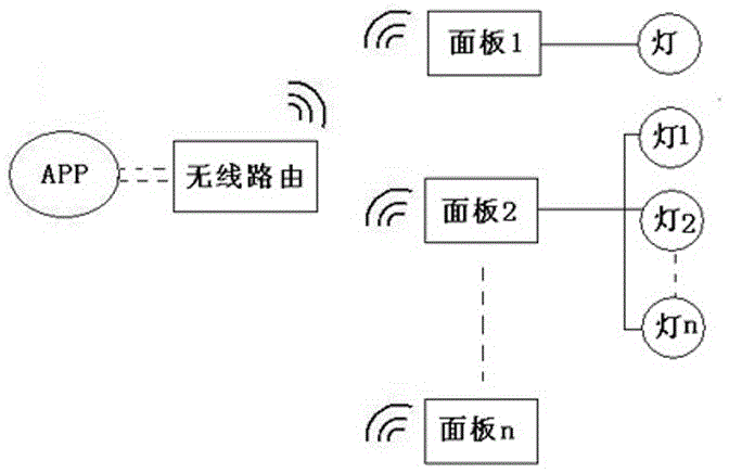
[0022] Please refer to figure 1 The schematic diagram of the system structure shown in the present invention is a panel and lamp control method based on closed carrier technology, including: the APP sends control commands to the panel through wireless devices, and the panel transmits signals to the lamps through a closed independent channel to realize control of the lamps. control;

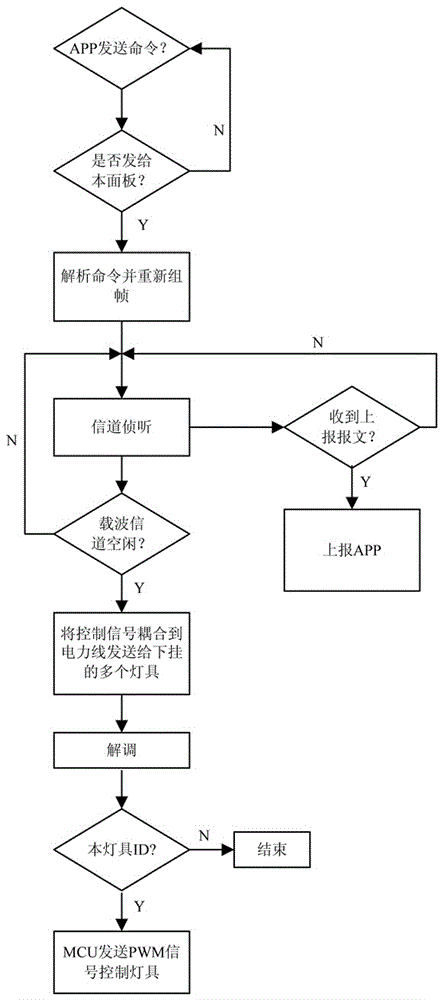
[0023] The specific steps are as follows, such as figure 2 Shown:

[0024] Step 11, the application program APP sends the command code to the panel through the wireless communication module of the handheld device according to the user operation: the APP transmits the control command to the panel with the wireless radio frequency module by driving the wireless radio module of the handheld device or the APP passes WIFI communicates with the gateway with WIFI module, and the gateway governs all the panels, and the gateway then deploys the corresponding panel to perform operations according to the ...


PUM


Abstract

The present invention provides a panel and lamp control method based on closed carrier technology, including the following steps: Step 11, APP sends a command code to the panel through the wireless communication module of the handheld device according to the user operation; Step 12, the panel receives the control After the signal, judge whether it is a signal sent to the panel, if yes, analyze the command, repackage the information, and seal the power line between the panel and the hanging lamps into an independent channel through a high-frequency band-stop filter. After the panel is monitored by the channel, the MCU modulates the digital signal into a carrier signal, couples it to the power line and sends it to multiple lamps hanging below, and replies to the APP with a confirmation frame; step 13, the lamp first demodulates after receiving the carrier signal, Restore it to a digital signal, and judge whether the ID is the ID of the lamp. If so, the MCU will send a PWM signal to control the lamp to realize dimming or switch the lamp according to the command. The closed carrier communication is adopted between the panel and the lamp system of the present invention, which has strong anti-interference and simple control and operation.

Description

technical field [0001] The invention relates to the field of lamp control of indoor AC power supply lines, and more specifically relates to a carrier communication method based on AC power supply lines and with a controllable communication range. Background technique [0002] Traditionally, the following technologies are generally used for dimming control of lamps: 1. Install a thyristor in the switch panel, and control the conduction angle of the thyristor through the knob on the panel to control the brightness of the lamp. 2. Two additional communication lines are laid between the panel and the lamp. The panel sends the dimming signal to the dimming controller of the lamp head through the communication line. 3. The communication between the panel and the lamp adopts the wireless radio frequency (RF) method to replace the communication line in 2, and the dimming is realized through the wireless method. [0003] The above methods have their own characteristics, but there ar...

Claims


Application Information

Patent Timeline
Patent Type & Authority Patents(China)
IPC IPC(8): H05B37/02
Inventor 吴丽文陈聪敏
Owner 厦门市致创能源技术有限公司
Why Eureka
Try Eureka