Tendon transmission artificial hand

A prosthetic hand and transmission wheel technology, applied in the field of tendon transmission prosthetic hand, can solve the problems of poor practicability and inability to achieve force grasping, etc., and achieve the effects of strong practicability, low processing cost and cost saving

Active Publication Date: 2014-11-26
SHENZHEN INST OF ADVANCED TECH CHINESE ACAD OF SCI
View PDF11 Cites 7 Cited by
  • Summary
  • Abstract
  • Description
  • Claims
  • Application Information

AI Technical Summary

Problems solved by technology

However, this technology can achieve fewer movements, and cannot reali...

Method used


Image

  • Tendon transmission artificial hand
  • Tendon transmission artificial hand
  • Tendon transmission artificial hand

Examples


Embodiment 1

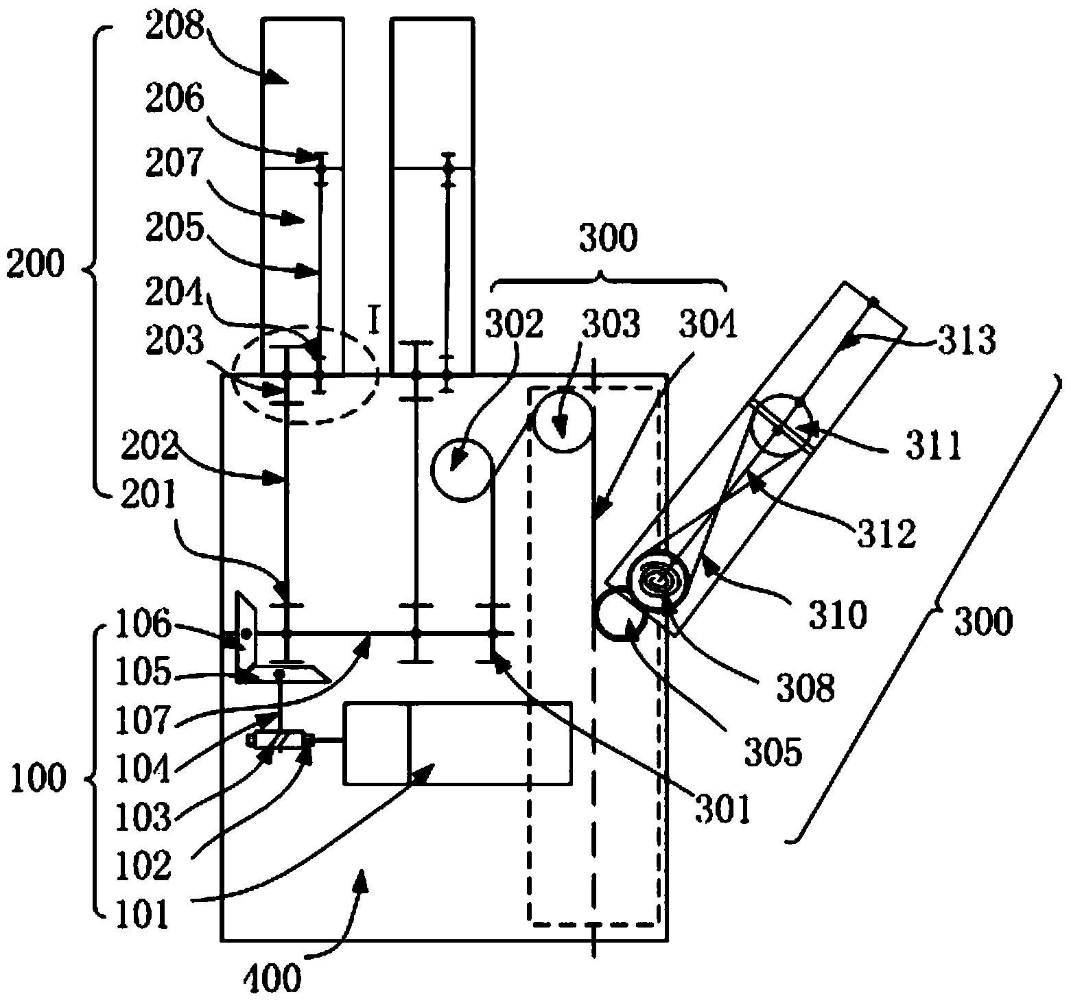
[0047] refer to figure 1 , the present embodiment provides a tendon-driven prosthetic hand, including a driving part 100 , a finger driving part 200 , a thumb driving part 300 and a palm cavity 400 , and the driving part 100 is installed in the palm cavity 400 .

[0048] The driving part 100 includes a gear motor 101 equipped with a drive shaft, a transmission mechanism and a total drive shaft 107 , one end of the transmission mechanism is connected to the drive shaft of the gear motor 101 , and the other end is connected to the total drive shaft 107 .

[0049] The geared motor 101 is arranged laterally in the palm cavity 400, and the geared motor 101 is an improved motor integrated with a motor and a reducer, in order to make the overall structure of the tendon-driven prosthetic hand more compact. In the geared motor 101, the motor is a DC brushless servo motor, and the reducer is a harmonic reducer.

[0050] This transmission mechanism comprises worm gear 102, worm screw 10...

Embodiment 2

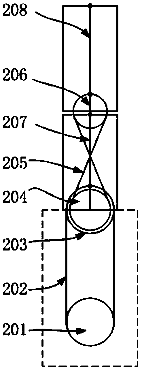
[0078] refer to figure 1 and Figure 7 The only difference between this embodiment and Embodiment 1 is that in this embodiment, the finger transmission part also includes a third finger transmission mechanism, a third finger knuckle 214 and a third finger joint shaft, and the third finger transmission mechanism includes a third finger transmission mechanism. Five finger transmission wheel 211, the sixth finger transmission wheel 213 and the third finger transmission tendon 212.

[0079] The fifth finger transmission wheel 211 is fixed on the second finger joint shaft and rotates coaxially with the fourth finger transmission wheel 206. The third finger transmission tendon 212 is a cross tendon rope, and the fifth finger transmission wheel 211 passes through the The third finger transmission tendon 212 transmits to the sixth finger transmission wheel 213, the sixth finger transmission wheel 213 is fixed on the third finger joint shaft, and the third finger joint shaft is instal...

Embodiment 3

[0082] The difference between this embodiment and Embodiment 1 is that the geared motor in this embodiment is arranged vertically, and the transmission mechanism of the driving part does not include the first bevel gear and the second bevel gear. Specifically, the transmission mechanism includes a worm gear and a worm screw, the drive shaft of the geared motor is connected to the worm screw, the worm screw meshes with the worm gear, and the worm gear is connected to the main drive shaft.

[0083] When the deceleration motor works, it drives the worm to move, and the worm is meshed with the worm gear, and then the worm gear is transmitted to the main drive shaft.


PUM


Abstract

The invention relates to a tendon transmission artificial hand comprising a drive part, a finger transmission part, a thumb transmission part and a palm cavity. The drive part is arranged inside the palm cavity and is provided with a drive motor, a transmission mechanism and a main drive shaft, and the finger transmission part and the thumb transmission part achieve finger flexion and extension movement through transmission wheels, transmission tendons and rotary shafts. The flexion and extension movement of three fingers can be achieved only by one motor, and compared with an artificial hand using more motors, the weight of the tendon transmission artificial hand is reduced. Meanwhile, the movement of the fingers is achieved mainly through a tendon transmission mechanism, and the machining cost of the tendon transmission parts is low, so that the cost of the artificial hand is lowered, and the artificial hand better adapts to requirements of consumers. In addition, as the drive parts are arranged in the palm cavity, wrist activities are not affected, and practicability of the artificial hand is enhanced.

Description

technical field [0001] The invention relates to the field of medical equipment, in particular to a tendon-driven artificial hand. Background technique [0002] Various natural disasters and accidents have resulted in an increasing number of amputees. Given the various pressures they are facing in life, many amputees hope to choose to wear artificial limbs to complete some corresponding actions and improve their employability. [0003] In 2011, Yves Losier and others from the University of New Brunswick, Canada, used low-cost, multi-degree-of-freedom (not less than 2 degrees of freedom), easy-to-control, and modular design as the commercial design of prosthetic hands in their research literature on UNB Hand. The goal, and the participating units include the Chicago Rehabilitation Institute, which is an international leader in this field in the United States. It can be seen that the current research direction on prosthetic hands is gradually developing towards commercializati...

Claims


Application Information

Patent Timeline
IPC IPC(8): A61F2/54
Inventor 匡星王子儒郑悦李光林
Owner SHENZHEN INST OF ADVANCED TECH CHINESE ACAD OF SCI
Why Eureka
Try Eureka