
System and method for distribution network fault locating based on improved double-terminal traveling wave method

A distribution network fault, double-terminal traveling wave technology, applied in the direction of fault location, information technology support system, etc., can solve the problems that the positioning reliability and positioning accuracy are difficult to guarantee, and the accuracy of fault traveling wave velocity cannot be guaranteed, and achieve high The effect of detection accuracy

Inactive Publication Date: 2014-11-26
STATE GRID CORP OF CHINA +1
View PDF4 Cites 36 Cited by
  • Summary
  • Abstract
  • Description
  • Claims
  • Application Information

AI Technical Summary

Problems solved by technology

[0005] Neither the fixed value nor the wave velocity measured off-line can guarantee the accuracy of the fault traveling wave velocity.
However, for the fault location method that uses the reflected wave at the fault point or the reflected wave at the opposite end bus to eliminate the influence of wave velocity, when the reflected wave is attenuated to the point where it cannot be measured or there is no reflected wave, its positioning reliability and positioning accuracy are difficult to guarantee.

Method used


Image

  • System and method for distribution network fault locating based on improved double-terminal traveling wave method
  • System and method for distribution network fault locating based on improved double-terminal traveling wave method
  • System and method for distribution network fault locating based on improved double-terminal traveling wave method

Examples


Embodiment Construction

[0051] The embodiments of the present invention will be described in further detail below in conjunction with the accompanying drawings. The following embodiments are only descriptive, not restrictive, and cannot limit the protection scope of the present invention.

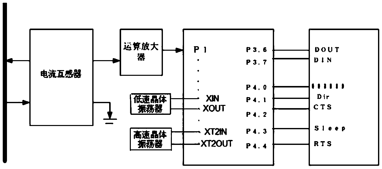
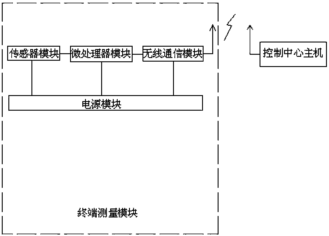
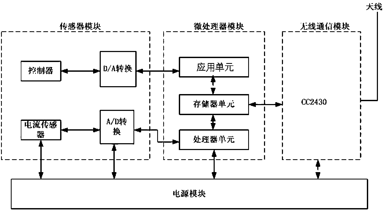
[0052] A distribution network fault location system based on the improved double-terminal traveling wave method, such as figure 1 As shown, it includes a terminal measurement module and a control center host composed of a sensor module, a microprocessor module, a wireless communication module, and a power supply module. The sensor module measures the current of each phase of the grid line, and the output of the sensor module The input is connected, the output of the microprocessor module is connected with the input of the wireless communication module, the output of the wireless communication module communicates wirelessly with the control center host, and the power supply module supplies power for the entire termi...


PUM


Abstract

The invention relates to a system and a method for distribution network fault locating based on an improved double-terminal traveling wave method. The system comprises a terminal measurement module and a control center host computer, wherein the terminal measurement module is composed of a sensor module, a microprocessor module, a wireless communication module and a power supply module. The method comprises the following steps: a current traveling wave signal measured by a current transformer is calculated to obtain each current phase with a time scale; the phase current is decoupled, and a line mode component is selected as a traveling wave propagation mode for fault locating; an obtained traveling wave signal is uploaded to the control center host computer; the head of a travelling wave is detected, and rapid intrinsic mode decomposition is carried out on the line mode component; the arrival time of the travelling wave is determined; the wave speed is measured; and a fault is located. By adopting the system and the method of the invention, higher detection accuracy is achieved, the consistency of wave speeds of a fault traveling wave in three line sections formed by a fault point and three measuring points is ensured, and accurate online fault traveling wave speed determination is realized.

Description

technical field [0001] The invention belongs to the technical field of distribution network fault location, in particular to a distribution network fault location system and method based on an improved double-terminal traveling wave method. Background technique [0002] Due to its complex topology, the distribution network has relatively high requirements for fault location. There are many traveling wave measurement algorithms based on measuring the time when the fault signal travels to the end to determine the fault point, the core of which is: 1. The capture of the signal, that is, the detection of the fault traveling wave head, is based on the characteristics of the fault signal using signal analysis 2. For the measurement of wave velocity, the accuracy of traveling wave velocity is another key factor for accurately locating the fault point by using the traveling wave method. The propagation speed of the fault traveling wave is related to the actual parameters of the tra...

Claims


Application Information

Patent Timeline
IPC IPC(8): G01R31/08
CPCY04S10/52
Inventor 王峥李国栋周雪松靳盘龙梁伟刘云王瑶
Owner STATE GRID CORP OF CHINA
Learn More