Shift register unit, gate drive circuit and display device

A shift register and gate connection technology, which is applied in the field of gate drive circuits, display devices, and shift register units, can solve the problems of reducing the stability and reliability of GOA circuits, and the output cannot be output normally.

Active Publication Date: 2014-11-26
BOE TECH GRP CO LTD +1
View PDF5 Cites 38 Cited by
  • Summary
  • Abstract
  • Description
  • Claims
  • Application Information

AI Technical Summary

Problems solved by technology

Therefore, the Output cannot be output normally, there...

Method used


Image

  • Shift register unit, gate drive circuit and display device
  • Shift register unit, gate drive circuit and display device
  • Shift register unit, gate drive circuit and display device

Examples


Embodiment Construction

[0028] The following will clearly and completely describe the technical solutions in the embodiments of the present invention with reference to the accompanying drawings in the embodiments of the present invention. Obviously, the described embodiments are only some, not all, embodiments of the present invention. Based on the embodiments of the present invention, all other embodiments obtained by persons of ordinary skill in the art without making creative efforts belong to the protection scope of the present invention.

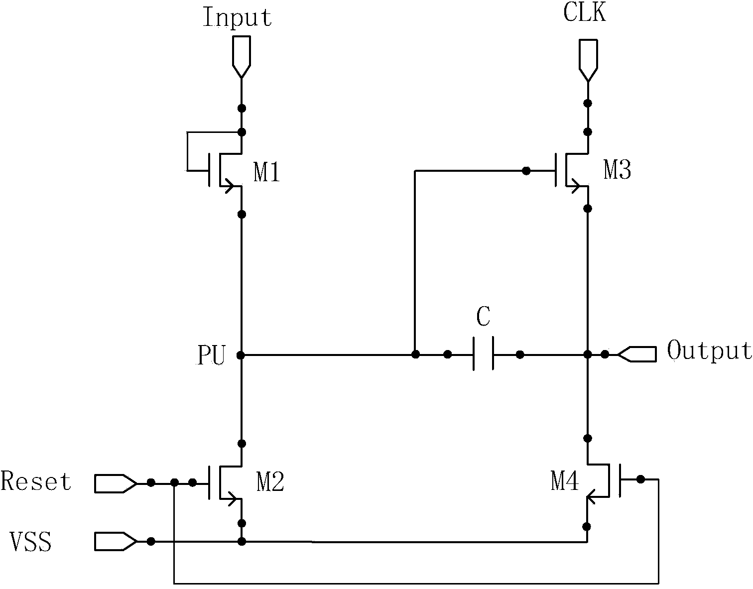
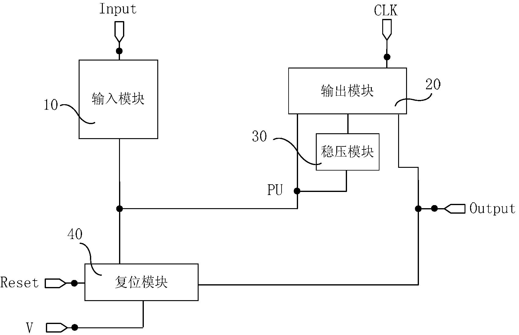
[0029] An embodiment of the present invention provides a shift register unit, such as figure 2 As shown, it may include: an input module 10 , an output module 20 , a voltage stabilizing module 30 and a reset module 40 .

[0030] Wherein, the input module 10 is respectively connected to the first signal input terminal Input and the pull-up control node PU, and is used for controlling the potential of the pull-up control node PU according to the signal input fr...


PUM


Abstract

The embodiment of the invention provides a shift register unit, a gate drive unit and a display device and relates to the technical field of display so as to prevent that a level of a pull-up control node which should be at a high-level state is mistakenly driven down. The shift register unit includes an input module, an output module, a voltage stabilizing module and a resetting module.

Description

technical field [0001] The invention relates to the field of display technology, in particular to a shift register unit, a gate drive circuit and a display device. Background technique [0002] Liquid Crystal Display (LCD for short) has the advantages of low radiation, small size and low power consumption, and is widely used in electronic products such as notebook computers, flat-screen TVs or mobile phones. [0003] The liquid crystal display is composed of interlaced pixel matrixes located in the horizontal and vertical directions. When the liquid crystal display is displayed, the data drive circuit can latch the input display data and clock signals in timing order, convert them into analog signals and input them to the liquid crystal panel. The gate drive circuit can convert the input clock signal into a voltage for controlling the on / off of pixels through the shift register, and apply it to the gate line of the liquid crystal panel row by row. [0004] In order to furth...

Claims


Application Information

Patent Timeline
IPC IPC(8): G09G3/36G11C19/28
Inventor 陈希薛海林
Owner BOE TECH GRP CO LTD
Why Eureka
Try Eureka