Antenna device and manufacturing method of antenna device

A technology for antenna devices and coils, applied to antenna supports/mounting devices, antennas, antenna parts, etc., can solve problems such as magnetic core cracks and changes in magnetic core characteristics, and achieve the effect of preventing cracks

Active Publication Date: 2017-11-10
SUMIDA CORP
View PDF1 Cites 0 Cited by
  • Summary
  • Abstract
  • Description
  • Claims
  • Application Information

AI Technical Summary

Problems solved by technology

However, there is a problem that the characteristics represented by the inductance of the magnetic core change due to the pressure applied to the magnetic core during molding or the shrinkage of the resin case after molding.
In addition, there is also the problem that the core is cracked due to the large pressure applied to the core during press molding.

Method used


Image

  • Antenna device and manufacturing method of antenna device
  • Antenna device and manufacturing method of antenna device
  • Antenna device and manufacturing method of antenna device

Examples


Embodiment Construction

[0046] Hereinafter, an antenna device 10 according to an embodiment of the present invention will be described with reference to the drawings.

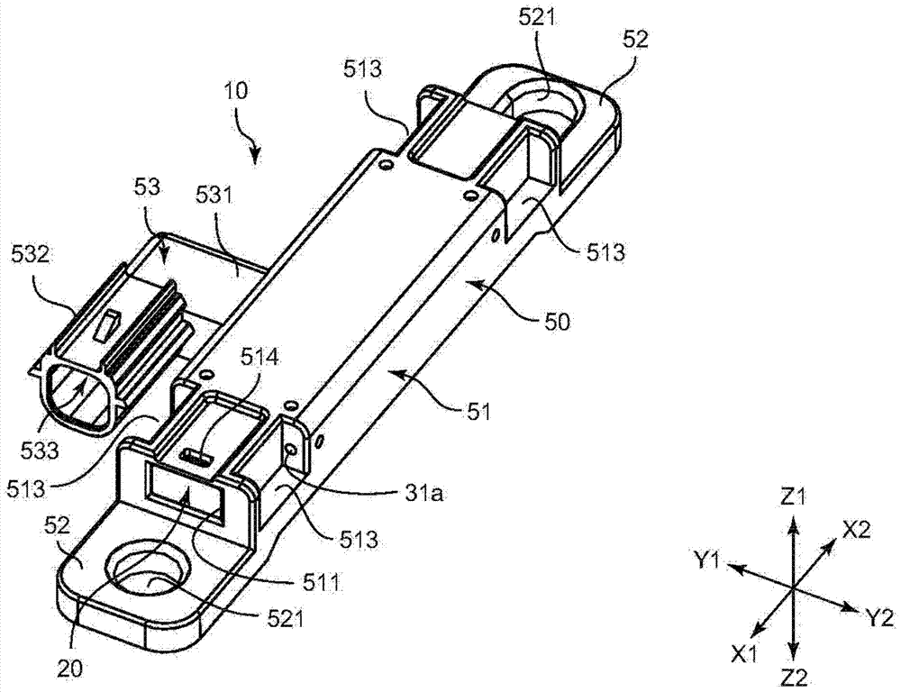
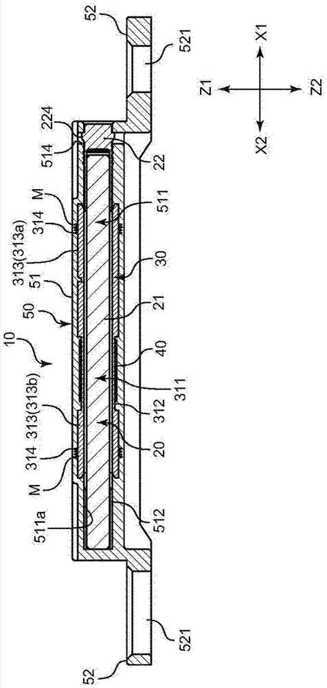
[0047] In addition, in the following description, let the side where the flange part 52 exists be a lower side (Z2 side), and let the opposite side be an upper side (Z1 side). In addition, the side where the opening of the insertion hole 511 exists is defined as one end side (X1 side), and the opposite side without the opening of the insertion hole 511 is defined as the other end side (X2 side). In addition, let the direction perpendicular to the X direction and the Z direction be the Y direction, and in figure 1 Let the left side be the Y1 side, and the opposite right side be the Y2 side.

[0048] figure 1 It is a perspective view showing the overall configuration of the antenna device 10 . figure 2 It is a side sectional view showing the structure of the antenna device 10 . like figure 1 and figure 2 As shown, the main struc...


PUM


Abstract

There is provided an antenna device capable of securing waterproof property while suppressing changes of characteristics of the core, and a manufacturing method of an antenna device. An antenna device 10 has: a core body 20 having a core 21 formed of a magnetic material, a bobbin 30 having an insertion through hole 311 in which the core body 20 is inserted, a coil 40 disposed in the vicinity of the bobbin 30, and a case 50 which covers the coil 40 in the vicinity of the bobbin 30 in a state of sealing from an outside, has an insertion hole 511 allowing the core body 20 to be inserted therein in a state of communicating with the insertion through hole 311, and retains the core body 20 inside the insertion hole 511 after the core body 20 is inserted.

Description

technical field [0001] The present invention relates to an antenna device and a method of manufacturing the antenna device. Background technique [0002] In recent years, antenna devices for receiving signals for locking and unlocking vehicle doors are increasingly mounted on vehicles. As such an antenna device, there is a device disclosed in Patent Document 1, for example. In the structure disclosed in Patent Document 1, after the coil is formed on the magnetic core (magnetic body), the case is formed by press molding so as to cover the outer peripheral side of the magnetic core. [0003] [Prior Art Literature] [0004] 【Patent Literature】 [0005] Patent Document 1: Japanese Patent Laid-Open Gazette, Japanese Patent Laid-Open No. 2006-121278 [0006] In the structure disclosed in Patent Document 1, since the case is formed by press molding so as to cover the outer peripheral side of the magnetic core, waterproof reliability of the coil portion is improved. However, th...

Claims


Application Information

Patent Timeline
Patent Type & Authority Patents(China)
IPC IPC(8): H01Q7/08H01Q1/24
CPCH01Q1/14H01Q1/3241H01Q1/3283H01Q1/40H01Q7/08
Inventor 岩崎纪阳马原繁
Owner SUMIDA CORP
Why Eureka
Try Eureka