
Organic electroluminescent device

a technology of electroluminescent devices and organic semiconductors, which is applied in the direction of discharge tubes/lamp details, discharge tubes luminescent screens, organic semiconductor devices, etc., to achieve the effect of increasing the driving voltage of the device, ensuring the film quality and performance of the light emitting unit, and initial luminan

Active Publication Date: 2013-10-15
SONY CORP
View PDF5 Cites 0 Cited by
  • Summary
  • Abstract
  • Description
  • Claims
  • Application Information

AI Technical Summary

Benefits of technology

[0013]Then, it is desirable to provide an organic electroluminescent device of a top emission configuration provided with a light transmissive upper electrode capable of devising to further improve initial characteristics and life characteristics of driving voltage and luminance.
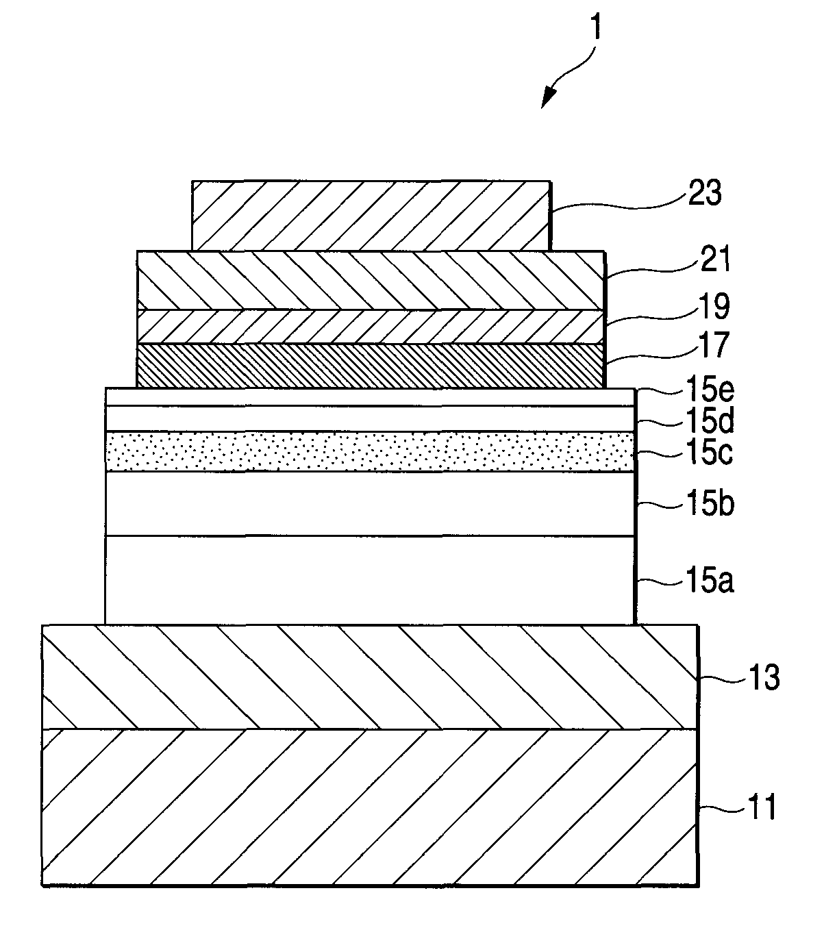
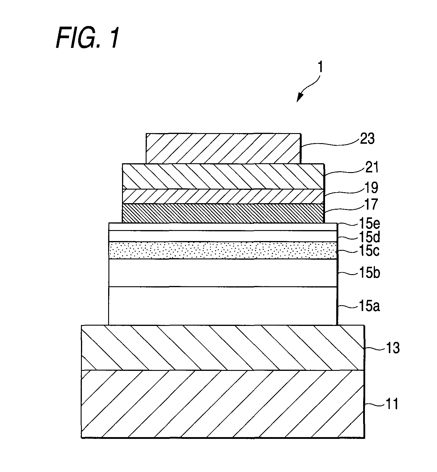
[0015]In the organic electroluminescent device of such a configuration, the connection layer and the charge transport layer which are interposed between the light emitting unit and the upper electrode become a barrier in forming the upper electrode to prevent the light emitting unit from damaging, thereby keeping film quality and performance of the light emitting unit. As will be explained in the Examples described later, it has been confirmed that as compared with a configuration in which a connection layer and a charge transport layer are not provided and a configuration in which only a connection layer is provided, according to the configuration of this embodiment of the invention, not only deterioration with time of luminance of and increase of driving voltage of the device are suppressed, but also initial luminance is high and driving voltage is controlled to a low level. Furthermore, according to the thus configured organic electroluminescent device, it has also been noted that a good device performance is kept without causing a lowering of the device performance due to the provision of the connection layer and the charge transport layer which become a barrier against the light emitting unit in forming the upper electrode.
[0016]In the light of the above, according to the organic electroluminescent device of the embodiment of the invention, change of properties of the light emitting unit due to the formation of the upper electrode can be prevented from occurring. As a result, even when a transparent conductive material to be formed by a sputtering method by which a base layer is largely influenced is used as the upper electrode, it is possible to keep the device performance good; and it is possible to devise to improve initial characteristics and long life characteristics of an organic electroluminescent device of a top emission type.

Problems solved by technology

However, even in any of organic electroluminescent devices of the foregoing configurations, in order to realize a display device using such an organic electroluminescent device, it is hardly said that initial characteristics and life characteristics of driving voltage and luminance are sufficient, and further improvements of the characteristics are demanded.

Method used


Image

  • Organic electroluminescent device
  • Organic electroluminescent device
  • Organic electroluminescent device

Examples


examples

[0048]Next, manufacturing procedures of each of organic electroluminescent devices of concrete Example according to an embodiment of the invention and Comparative Examples 1 and 2 against this Example are described.

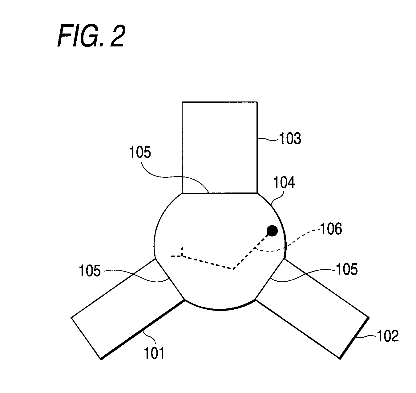
[0049]Incidentally, a vacuum device as illustrated in FIG. 2 was used in the preparation of each of organic electroluminescent devices of the Example and Comparative Examples. A vacuum device 100 as illustrate in FIG. 2 is provided with a vapor deposition compartment 101, a sputtering compartment 102, a glove box compartment 103, and a carrier compartment 104 connected to each of them. A door 105 is provided between the carrier compartment 104 and each of the compartments 101 to 103 for the purpose of isolating a gas atmosphere in the inside thereof. A robot arm 106 is set up within the carrier 104 for the purpose of carrying a treating substrate into each of the compartments 101 to 103 via the carrier compartment 104. Thus, in the vacuum device 100, the treatment can be ...


PUM


Abstract

An organic electroluminescent device provided with a lower electrode formed on a substrate, a light emitting unit having at least an organic light emitting layer and formed on the lower electrode, and a light transmissive upper electrode formed on the light emitting unit, wherein a connection layer for supplying a charge into the light emitting unit and a charge transport layer having charge transporting properties of a reverse conducting type against a charge to be injected from the upper electrode are stacked in this order from a side of the light emitting unit between the light emitting unit and the upper electrode.

Description

CROSS REFERENCES TO RELATED APPLICATIONS[0001]The present invention contains subjects related to Japanese Patent Application JP 2006-030576 filed in the Japan Patent Office on Feb. 8, 2006, the entire contents of which being incorporated herein by reference.BACKGROUND OF THE INVENTION[0002]1. Field of the Invention[0003]The invention relates to an organic electroluminescent device. In particular, the invention relates to an organic electroluminescent device which is suitable for a so-called top emission type for extracting emitted light from a side opposite to a substrate on which the device is formed.[0004]2. Description of the Related Art[0005]An organic electroluminescent device (so-called organic EL device) is a device of a self-luminous type having a light emitting layer made of an organic compound between an anode and a cathode and is watched as a device capable of realizing a large-area display device of low-voltage driving. In a display device using such an organic electrolu...

Claims


Application Information

Patent Timeline
Patent Type & Authority Patents(United States)
IPC IPC(8): H01J1/62H01J63/04
CPCH01L51/50H01L51/5068C09K11/06H05B33/14H01L51/0081H01L51/5048H01L51/5088H01L51/5234H01L2251/5315C09K2211/1007C09K2211/1011C09K2211/1014C09K2211/1029C09K2211/186H10K85/324H10K50/00H10K50/14H10K50/157H10K50/17H10K50/828H10K2102/3026
Inventor NAKAMURA, AKIFUMI
Owner SONY CORP
Learn More