
Gas charge container, atom probe apparatus, and method for analyzing hydrogen position in material

a hydrogen position and gas charge technology, applied in the field of gas charge containers, atom probe apparatus, and methods for analyzing hydrogen positions in materials, can solve problems such as hydrogen embrittlement, weakening the bonding force between atoms, and countermeasures taken

Active Publication Date: 2013-10-29
NIPPON STEEL CORP
View PDF16 Cites 0 Cited by
  • Summary
  • Abstract
  • Description
  • Claims
  • Application Information

AI Technical Summary

Benefits of technology

The present invention provides a method and apparatus for measuring the position of hydrogen in a material using an atom probe. By charging deutrium gas in the apparatus and rapidly cooling the material, the charged deutrium is prevented from escaping and contamination of the sample can be suppressed. This enables accurate and efficient measurement of hydrogen positions in materials, including steel materials, and helps improve the reliability of materials design. The invention contributes to the development of materials science and the identification of hydrogen positions in materials.

Problems solved by technology

Meanwhile, hydrogen in a steel material causes hydrogen embrittlement (delayed fracture or the like), and countermeasures for this have been taken for a long period of time.
It is considered that the hydrogen which has entered the steel becomes a starting point (generation of a crack) of a fracture such that the hydrogen diffuses in the steel, moves and accumulates to a specific spot, and weakens the bonding force between atoms or the like.
The hydrogen embrittlement is a problem in a number of metallic materials as well as steel.
Although hydrogen in a steel material is a very important element in determining the reliability of the material, the hydrogen cannot be identified by direct observation.
However, although the trapped energy and abundance of hydrogen can be estimated, both the methods cannot directly investigate the existence position of hydrogen.
In steel materials containing a fine precipitate of 0.1 μm or less, though the fine precipitate is considered that the hydrogen trapping capacity is high, it was impossible to investigate in which portion hydrogen exists.
However, since emulsion is used in all of them, there is no spatial resolution of 0.1 μm or less.
Therefore, the determination where hydrogen exists in the steel material could not be made.
However, even if a needle-shaped material is worked in advance and hydrogen is charged into this needle-shaped material, a phenomenon which the charged hydrogen diffuses in a short time which is taken until the needle-shaped material is introduces into the 3DAP apparatus, and escapes from the surface of the needle-shaped material occurs in a very short time.
Therefore, analysis was difficult.
In an ordinary apparatus, however, a long period of time of 20 minutes or more is required until the sample is cooled to this temperature.
Hence, since the deutrium charged until the cooling escaped from the sample, observation of the existence position of hydrogen to be targeted was difficult.

Method used


Image

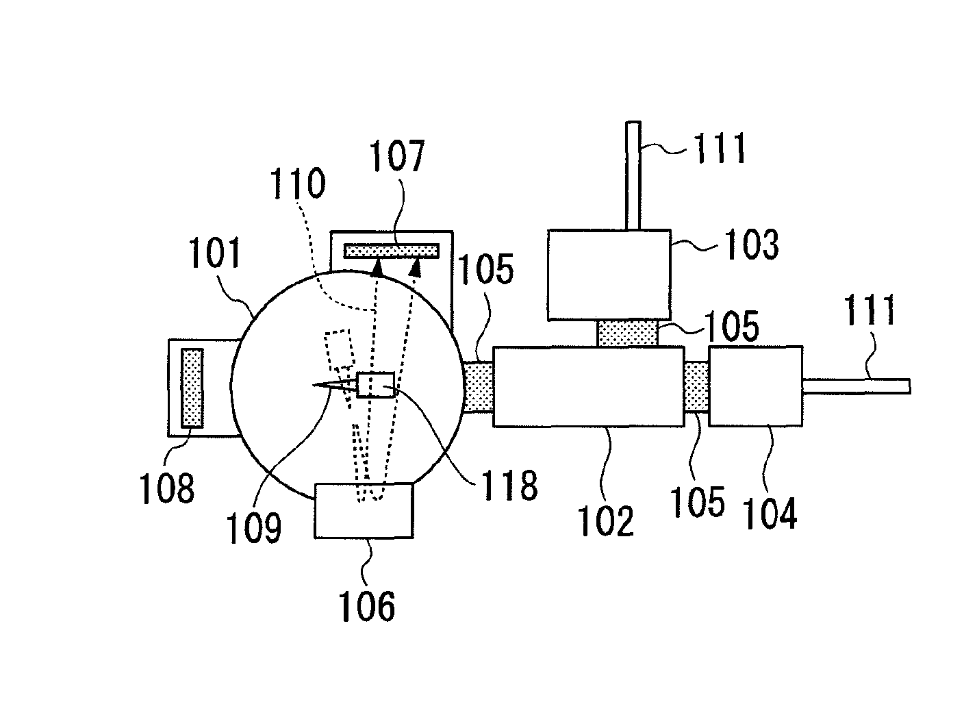
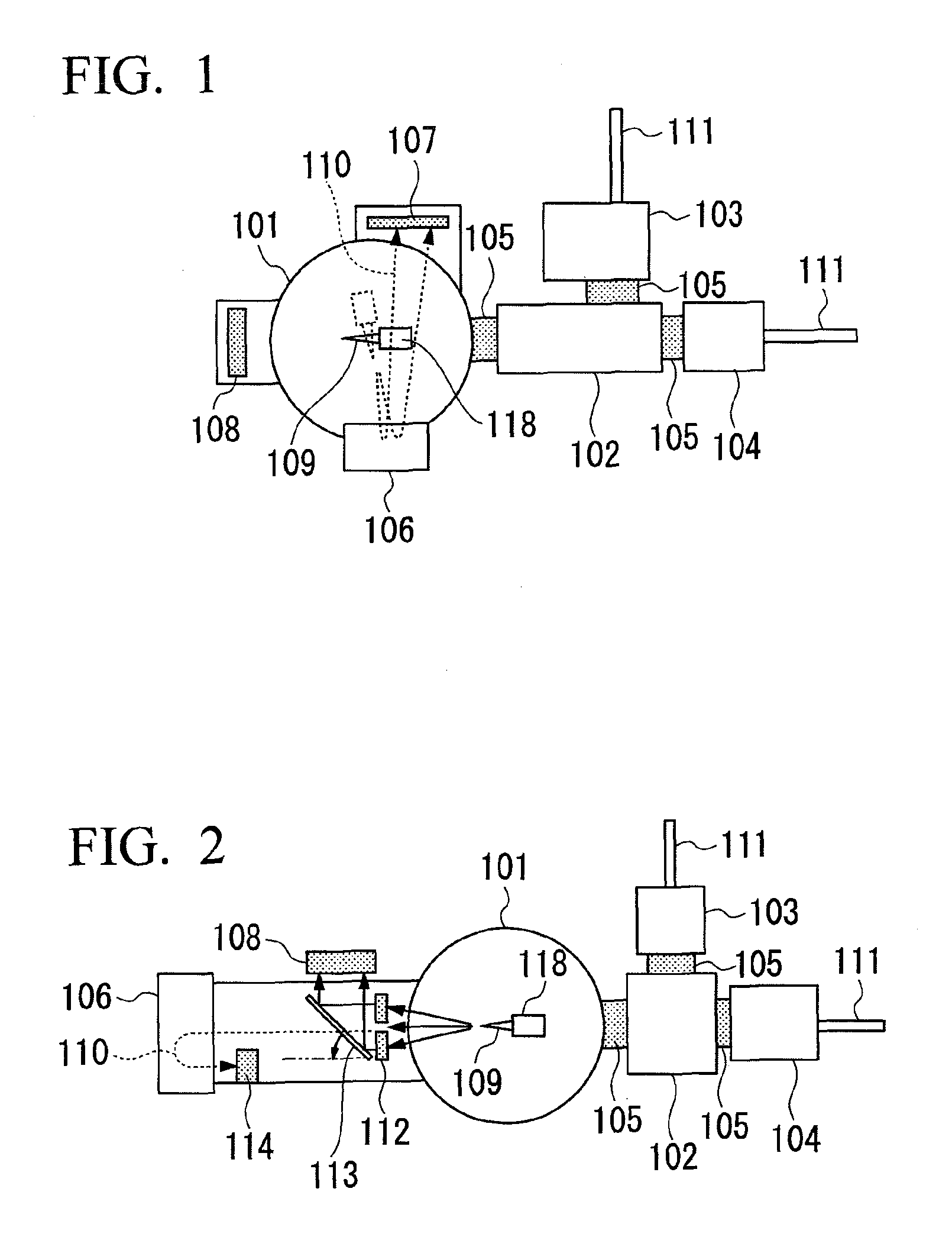
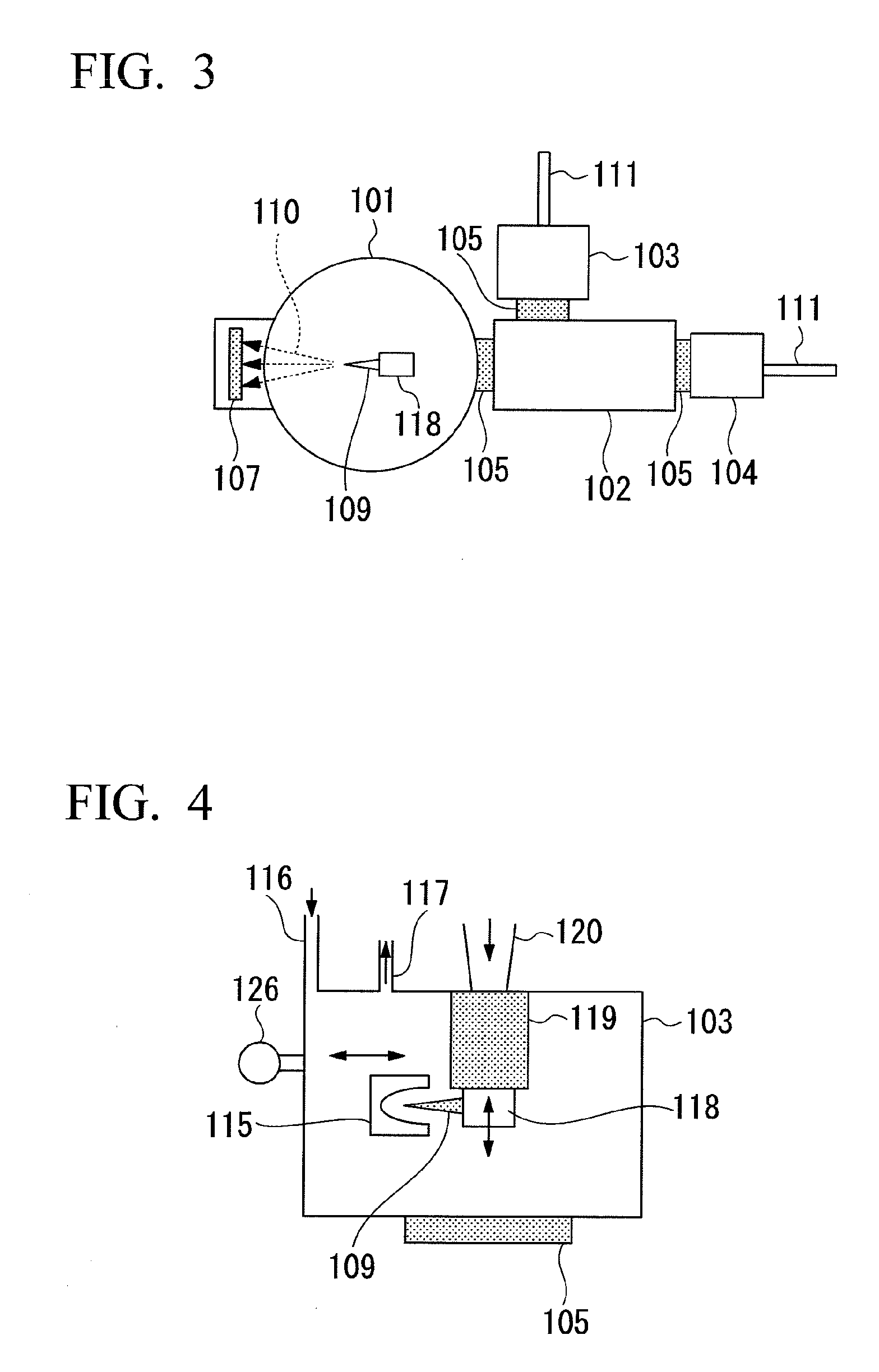
  • Gas charge container, atom probe apparatus, and method for analyzing hydrogen position in material
  • Gas charge container, atom probe apparatus, and method for analyzing hydrogen position in material
  • Gas charge container, atom probe apparatus, and method for analyzing hydrogen position in material

Examples


example 1

[0102]In order to investigate the temperature of the needle-shaped material 109 during the deutrium charge, a sample holder 118 for measurement resembling a needle-shaped material 109 was prepared in accordance with the actual needle-shaped material 109 and the sample holder 118 using the gas charge container 103 shown in FIG. 4 so that the tip of a thermocouple was located at a position 10 mm apart from the sample holder 118, and temperature measurement was performed. The inside of the gas charge container 103 shown in FIG. 4 was evacuated to 2×10⁻⁸ Torr (2.6×10⁻⁶ Pa) from an evacuation line 117 by a pump.

[0103]In this state, liquid nitrogen was poured into a liquid nitrogen container 120, and the cold finger 119, and the sample holder 118 and the needle-shaped material 109 which were brought into contact with the cold finger were cooled. The temperature of the needle tip of the needle-shaped material 109 became −115° C. about 40 minutes after the start of the cooling. The deutrium...

example 2

[0106]A needle-shaped material 109 made of a drawn pearlite steel wire worked with the radius of curvature of the needle tip being 50 nm was attached to the sample holder 118 as shown in FIG. 4, and was introduced into the sample introduction container 104 used in Example 1. Then, the sample holder 118 was transferred into the gas charge container 103 shown in FIG. 4 along with the needle-shaped material 109, using the transfer rod 111, and the needle-shaped material heater 115 was arranged near the needle-shaped material 109.

[0107]The inside of the gas charge container 103 was evacuated to a high vacuum of 2×10⁻⁸ Torr (2.6×10⁻⁶ Pa) by an evacuation line 117. Thereafter, the cold finger 119 of the liquid nitrogen container 120 into which liquid nitrogen was introduced was brought into close contact with the sample holder 118, and the sample holder 118 was cooled to −180° C. In this state, the deutrium was charged into the needle-shaped material 109 by introducing the deutrium gas fr...

example 3

[0109]A needle-shaped material 109 made of precipitate-dispersed steel worked with the radius of curvature of the needle tip being 60 nm was attached to the sample holder 118, and was introduced into the sample introduction container 104 of the apparatus of the present invention. Then, the needle-shaped material 109 was arranged in a heating position of the needle-shaped material 109 by transferring the sample holder 118 into the gas charge container 103 shown in FIG. 5 along with the needle-shaped material 109, using the transfer rod 111.

[0110]After the inside of the gas charge container 103 was evacuated to a high vacuum by the evacuation line 117, the sample holder 118 was screwed into the cold finger 119 which was cooled by operating the refrigerator 121, and the sample holder 118 was cooled to −200° C.

[0111]In this state, the deutrium was charged into the needle-shaped material 109 by introducing the deutrium gas to 600 Torr (7.98×10⁴ Pa) from the deutrium gas introduction line...


PUM

PropertyMeasurementUnit
temperatureaaaaaaaaaa

Abstract

A gas charge container includes a sample holder which holds a needle-shaped material, a deutrium gas supply portion which charges a deutrium gas into the needle-shaped material held by the sample holder, and a heating portion which heats the needle-shaped material held by the sample holder. The needle-shaped material is cooled by blocking the heat generated by the heating portion after the needle-shaped material is heated by the heating portion.

Description

BACKGROUND OF THE INVENTION[0001]1. Field of the Invention[0002]The present invention relates to a gas charge container, an atom probe apparatus, and a method for analyzing a hydrogen position in a material. Particularly, the present invention relates to a technique which directly measures atoms of a sample one by one, thereby improving the functions of an atom probe apparatus which can investigate the atomic structure of a very minute region. According to this technique, since the existence position of hydrogen in a material which was conventionally difficult to observe can be directly observed, the technique can greatly contribute to development of materials with excellent hydrogen embrittlement resistance.[0003]Priority is claimed on Japanese Patent Application No. 2008-164619 filed on Jun. 24, 2008 and Japanese Patent Application No. 2009-115426 filed on May 12, 2009, the contents of which are incorporated herein by reference.[0004]2. Description of Related Art[0005]As introduce...

Claims


Application Information

Patent Timeline
Patent Type & Authority Patents(United States)
IPC IPC(8): G01N9/00
CPCG01N23/2255H01J37/20H01J37/285H01J2237/006H01J2237/2001
Inventor TAKAHASHI, JUNKAWAKAMI, KAZUTOOHMORI, HARUO
Owner NIPPON STEEL CORP
Learn More