Bent contact member, jack module and electrical connector

A contact, bending technology, applied in the direction of contact parts, connections, parts of connecting devices, etc., can solve problems such as increasing the insertion loss between the plug and the socket

Active Publication Date: 2014-11-26
CHINA AVIATION OPTICAL-ELECTRICAL TECH CO LTD
View PDF4 Cites 34 Cited by
  • Summary
  • Abstract
  • Description
  • Claims
  • Application Information

AI Technical Summary

Problems solved by technology

The contact model of the curved contact 103 and the socket contact 101 is as follows figure 2 As shown, assuming that the curved contact 103 and the socket contact 101 each use the front end as the plug-in end, it can be seen from the figure that the front of the curved contact 103 gradually assumes a downwardly inclined structure, and the front end has a An upward-turned flange, when the plug is mated with the socket, the bent contact 103 o

Method used


Image

  • Bent contact member, jack module and electrical connector
  • Bent contact member, jack module and electrical connector
  • Bent contact member, jack module and electrical connector

Examples


Embodiment Construction

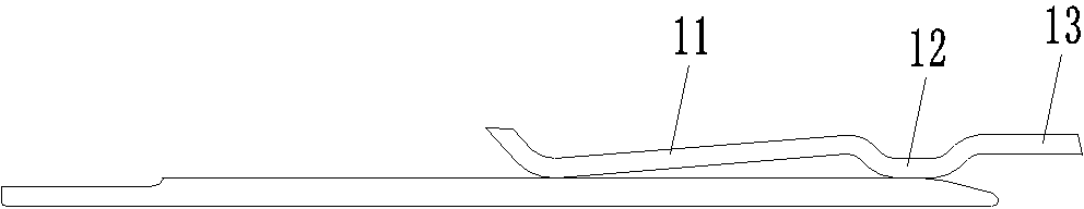
[0024] Example 1 of the bent contact, such as image 3 As shown, the contact piece takes the front end as the plug-in end, which includes a plug-in part 11, a concave part 12 and a horizontal mounting part 13 located behind the plug-in part, and the plug-in part 11, concave part 12 and mounting part 13 are from front to back Set in turn. Wherein, the front end of the insertion part 11 has a flange formed by turning upwards, and the lower side of the flange is formed as a front contact part for contacting with the matching contact piece. In this embodiment, the concave part 12 is U-shaped. And relative to the rear end of the socket part 11, it is recessed downwards, and its lower side forms the rear contact part of the contact piece. The mounting part 13 is horizontally located at the rear end of the recessed part 12. The position is gradually inclined downward from the back to the front. In this embodiment, the front and rear contact parts are located on the same horizontal p...


PUM


Abstract

The invention relates to the field of electrical connectors, and especially relates to a bent contact member, a jack module and an electrical connector. The front end of the bent contact member is used as a plugging end. The bent contact member comprises a plugging part and a horizontal mounting part disposed behind the plugging part. The front end of the plugging part is provided with a flanging formed through upward bending. The lower side of the bend of the flanging forms a front contact part used for contacting a matching contact member. A concave part which is concave downward relative to the plugging part is arranged between the plugging part and the mounting part. The concave part forms a rear contact part of the contact member. The plugging part gradually slopes downward from back to front from the joint of the plugging part and the concave part. Before use, the front and rear contact parts can be respectively in contact with the root and the end of the matching contact member, so that the formation of a cantilever structure on the matching contact member is avoided or the length of the cantilever of the matching contact member is shortened at least, thereby reducing the insertion loss of a differential connector. In conclusion, the bent contact member can reduce the insertion loss between a plug and a socket of a differential connector.

Description

technical field [0001] The invention relates to the field of electrical connectors, in particular to an angled contact piece, a socket module and an electrical connector. Background technique [0002] Differential connector assemblies are often applied to occasions that require high-speed, high-quality transmission signals, including plugs and sockets, plugs include plug housings, metal shields, and jack modules, jack modules include insulators, bent contacts, and connectors The floor and the bent contacts are divided into signal contacts and ground contacts, and the signal contacts and the ground contacts are arranged in pairs and arranged alternately. The socket includes a socket housing and a socket contact. The socket contact is a straight contact. The insulator of the plug is provided with an insertion hole for the socket contact to be inserted into. The bent contact is located in the corresponding insertion hole. [0003] The mating state of the plug and socket of the...

Claims


Application Information

Patent Timeline
IPC IPC(8): H01R13/02H01R13/11
CPCH01R13/518
Inventor 周国奇袁俊峰赵越超
Owner CHINA AVIATION OPTICAL-ELECTRICAL TECH CO LTD
Why Eureka
Try Eureka