Supercharge Your Innovation With Domain-Expert AI Agents!

A switching power supply dual current control circuit

A technology for controlling circuits and switching power supplies. It is applied in the direction of control/regulation systems, electrical components, and adjustment of electrical variables. It can solve problems such as transformer bias, circuit instability, and large slope compensation, and achieve precise and simple control. , to prevent the effect of saturation

Active Publication Date: 2018-11-27
南京创佳通讯电源设备有限公司
View PDF6 Cites 0 Cited by
  • Summary
  • Abstract
  • Description
  • Claims
  • Application Information

AI Technical Summary

Problems solved by technology

In recent years, due to the difficulty in realizing the synchronous non-distortion slope compensation technology necessary for large duty cycle and poor anti-noise performance, current mode control is facing the challenge of voltage mode control with improved performance
[0003] There are also certain defects in the peak current mode control. Because the peak current waveform of the primary side or the secondary side is compared with a fixed value, the anti-interference ability is very weak, and the output circuit cannot be directly controlled, and a large slope compensation is required.
[0004] The average current control mode uses the output current waveform of the secondary side to compare with the voltage deviation value, and has good output current control, but when there is leakage inductance or resonant inductance in the circuit, it cannot control the peak current of the primary side well, and it is easy to Excessive switch current or transformer bias
[0005] As we all know, the use of voltage control mode has problems such as circuit instability, transformer bias, etc., which is not good for circuit protection, and has a smaller bandwidth compared with peak current mode control PWM, so it is rarely used

Method used


Image

  • A switching power supply dual current control circuit
  • A switching power supply dual current control circuit

Examples


Embodiment Construction

[0017] In order to deepen the understanding of the present invention, the present invention will be further described below in conjunction with the embodiments and accompanying drawings. The embodiments are only used to explain the present invention and do not constitute a limitation to the protection scope of the present invention.

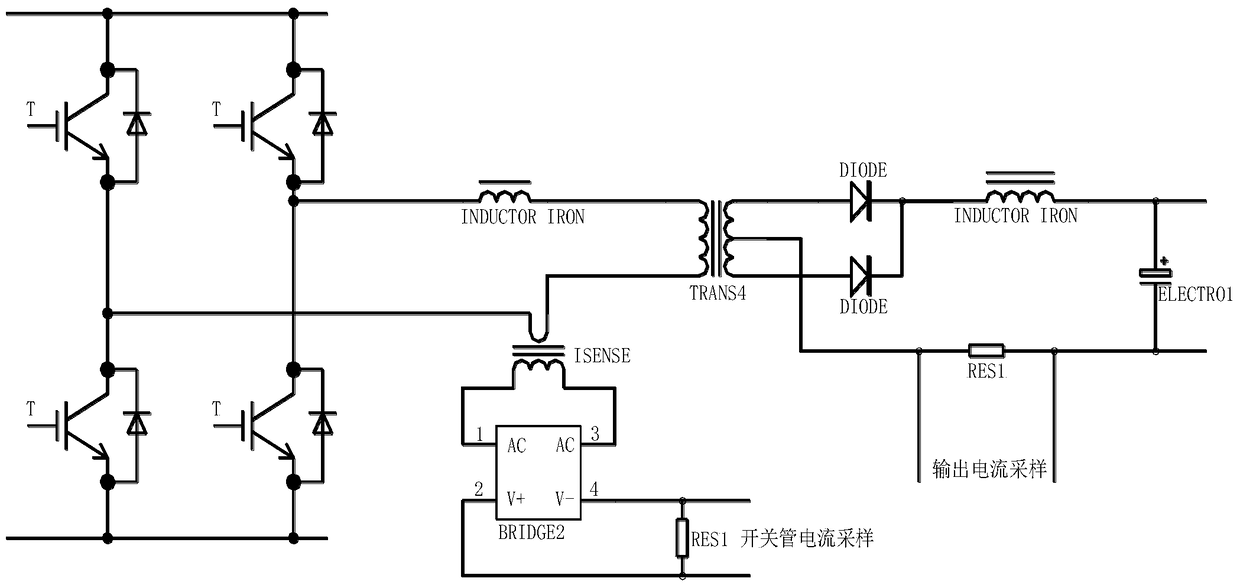
[0018] see figure 1 In the dual-current control circuit of the switching power supply shown, an inductor, a transformer and a switching tube are connected in series between the nodes at both ends of the primary side circuit connected to the two poles of the bus bar through two single-pole single-position switches, and the switching tube is provided with a switching tube current The sampling device, the current sampling device of the switch tube is a current sampling transformer, which is used to detect the magnitude of the switch current on the primary side of the transformer where the switch tube is located. The two AC input pins 1 and 3 of the ...


PUM


Abstract

The invention discloses a double-current control circuit of a switching power supply. A switching tube current sampling device is arranged on a circuit primary edge. An output current sampling device is arranged on a circuit auxiliary edge. An error amplifier compares primary error signals generated by reference voltage and output voltage passing through a sampling network, and the error signals, auxiliary edge output current detected by the output current sampling device and switching current detected by the switching tube current sampling device are connected to the error amplifier together to generate secondary error signals. The secondary error signals are connected to a PWM comparator to generate PWM pulses and adjust the circuit output. According to the double-current control circuit of the switching power supply, switching current signals of a primary edge switching tube are simply introduced into an average current control mode to control the switching power supply so that order reduction can be conducted on a control loop due to the average current control mode, and the current of a primary edge switch can be controlled in real time. In addition, slope compensation does not need to be additionally introduced, and control can be more timely and more accurate.

Description

technical field [0001] The invention relates to a current mode control circuit, in particular to a switching power supply dual current control circuit. Background technique [0002] The protection circuit of the general power supply adopts the peak current control mode. In the late 1960s, it was derived from the single-ended self-excited switching power supply with the primary side current protection function. It was not studied in depth until the early 1980s. With the emergence of the first batch of current mode control PWM integrated circuits, the current mode control was rapidly popularized and applied, mainly for single-ended and push-pull circuits. In recent years, due to the difficulty in realizing the synchronous undistorted slope compensation technology necessary for large duty cycle and poor anti-noise performance, current mode control is facing the challenge of voltage mode control with improved performance. [0003] The peak current mode control also has certain ...

Claims


Application Information

Patent Timeline
Patent Type & Authority Patents(China)
IPC IPC(8): H02M3/335
Inventor 彭宪奇
Owner 南京创佳通讯电源设备有限公司
Features
  • R&D
  • Intellectual Property
  • Life Sciences
  • Materials
  • Tech Scout
  • Unparalleled Data Quality
  • Higher Quality Content
  • 60% Fewer Hallucinations
Learn More