Camera installation mechanism with anti-explosion function

A technology of installation mechanism and camera, applied in the camera body, photography, camera and other directions, can solve the problem of inability to meet the needs, and achieve the effect of perfect explosion-proof effect, improve camera effect, and excellent monitoring effect.

Inactive Publication Date: 2014-11-26
JING LIN CHENGDU SCI & TECH
View PDF14 Cites 3 Cited by
  • Summary
  • Abstract
  • Description
  • Claims
  • Application Information

AI Technical Summary

Problems solved by technology

However, the installation mechanisms currently in use are all used under normal conditions and cannot meet the needs of this specific environment.

Method used


Image

  • Camera installation mechanism with anti-explosion function

Examples


Embodiment 1

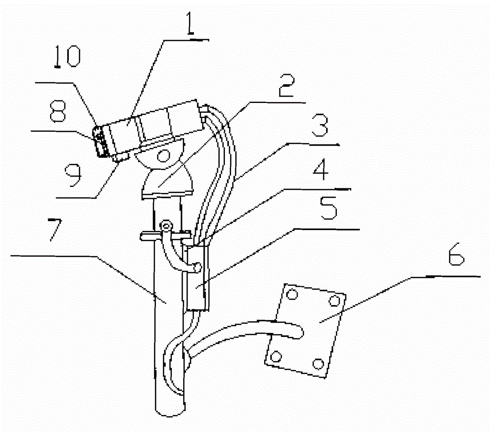
[0018] Such as figure 1 As shown, the present invention includes an explosion-proof shield 1, an explosion-proof electric platform 2, a junction box 5, a mounting base plate 6, a mounting bracket 7 and a wiper 8, and the explosion-proof shield 1 is installed on the top of the explosion-proof electric platform 2, and the explosion-proof electric platform The bottom of the cloud platform 2 is installed on the mounting bracket 7, and a wiper 8 is also installed on the end face of the explosion-proof shield 1; a fixed steel plate 4 is also welded on the side of the mounting bracket 7, and the junction box 5 is fixedly installed on the fixed steel plate 4. The bottom side wall of the mounting bracket 7 is also provided with a mounting base plate 6, and the mounting bracket 7 can rotate around the connection end of the mounting base plate 6; the explosion-proof flexible pipe is connected between the explosion-proof shield 1 and the explosion-proof electric pan-tilt 2 and the junction...

Embodiment 2

[0021] The preferred specific structure of this embodiment on the basis of Embodiment 1 is as follows: the explosion-proof shield 1 is a hollow cuboid shield, and the infrared lamps 10 are distributed around the inner wall of the explosion-proof shield 1 and evenly distributed. Ensure that there is enough space inside to install the camera and infrared lamps. The uniformly distributed infrared lamps can give uniform infrared light to the camera installed in the middle of the explosion-proof shield to ensure the best monitoring effect at night.

[0022] The light sensor 9 is an HA2003 light sensor.

[0023] The thickness of the fixed steel plate 4 is between 6-7mm. It can better realize the fixing of the junction box, and make the junction box have better explosion-proof ability.

[0024] The junction box 5 is also connected with power lines.


PUM


Abstract

The invention discloses a camera installation mechanism with the anti-explosion function. The camera installation mechanism with the anti-explosion function comprises an anti-explosion shield, an anti-explosion electrical platform, a junction box, an installation base plate, an installation support and a windshield wiper, wherein the anti-explosion shield is installed on the top of the anti-explosion electrical platform, the bottom of the anti-explosion electrical platform is installed on the installation support, and the windshield wiper is further installed on the end face of the anti-explosion shield; a fixed steel plate is further welded to the side face of the installation support, the junction box is fixedly installed on the fixed steel plate, the installation base plate is arranged on the side wall of the lower portion of the installation support, and the installation support can rotate around the connecting end of the installation base plate; anti-explosion flexible pipes are installed between the anti-explosion shield and the junction box and between the anti-explosion electrical platform and the junction box; an illumination sensor is installed on the bottom of the anti-explosion shield, multiple infrared lamps are arranged on the inner wall of the anti-explosion shield, all the infrared lamps are connected with the illumination sensor, and the illumination sensor is connected to the junction box through the anti-explosion flexible pipes. By the adoption of the structure, the camera installation mechanism has the anti-explosion capacity and is quite suitable for the places containing combustible gas or an explosive mixture of steam and air or containing combustible dust mixtures, and the excellent monitoring effect can also be guaranteed at night by the adoption of the mechanism.

Description

[0001] technical field [0002] The invention relates to the field of camera installation, in particular to a camera installation mechanism with an explosion-proof function. Background technique [0003] In the processing places of petroleum, chemical industry, mine, military industry, medicine, oil depot, ship, drilling platform, gas station, fireworks production, grain processing and storage, etc., there are explosive mixtures formed by flammable gas or steam and air, or containing Combustible dust mixture, the mechanism used to install the camera in this kind of place needs to have good explosion-proof ability, otherwise it will be easily damaged and cannot work normally in such a working environment. At the same time, in the industrial TV monitoring system, we hope to ensure excellent monitoring effect even at night. And the installation mechanism that uses now is to use under routine conditions, can't satisfy the needs under this kind of specific environment. Content...

Claims


Application Information

Patent Timeline
Patent Type & Authority Applications(China)
IPC IPC(8): H04N5/225G03B17/02G03B15/05
Inventor 曾衡东
Owner JING LIN CHENGDU SCI & TECH
Why Eureka
Try Eureka