Chip mounter and bottom lens visual system thereof

A vision system and placement machine technology, applied in optics, instruments, photography, etc., can solve the problems of affecting the speed of image recognition, time-consuming multiple images, and time-consuming image processing, so as to shorten the image processing time and avoid unclear images. , the effect of reducing the number of photos

Active Publication Date: 2014-11-26
泰姆瑞(北京)精密技术有限公司
View PDF9 Cites 12 Cited by
  • Summary
  • Abstract
  • Description
  • Claims
  • Application Information

AI Technical Summary

Problems solved by technology

The existing mounter bottom mirror vision system has the following disadvantages: 1. The structure of the bottom mirror vision system is a bottom mirror camera, which sequentially takes pictures of multiple placement heads. At the beginning of the film, the camera will take pictures 4 times, which not only takes a long time to take pictures, but also takes time when processing multiple images
2. The camera control adopts the software control method. When the single axis moves to the position where the patch head to be processed moves directly above the bottom mirror camera, an instruction is given to the software. After receiving this instruction, the software sends a trigger signal to the bottom mirror camera to realize a photoshoot. Image processing is time consuming due to software processing
4. If the camera movement speed is increased to reduce the time for taking pictures, the camera movement speed is faster, which will cause image smearing and affect the image recognition speed

Method used


Image

  • Chip mounter and bottom lens visual system thereof
  • Chip mounter and bottom lens visual system thereof

Examples


Embodiment Construction

[0025] The present invention will be described in further detail below in conjunction with specific examples, but not as a limitation of the present invention.

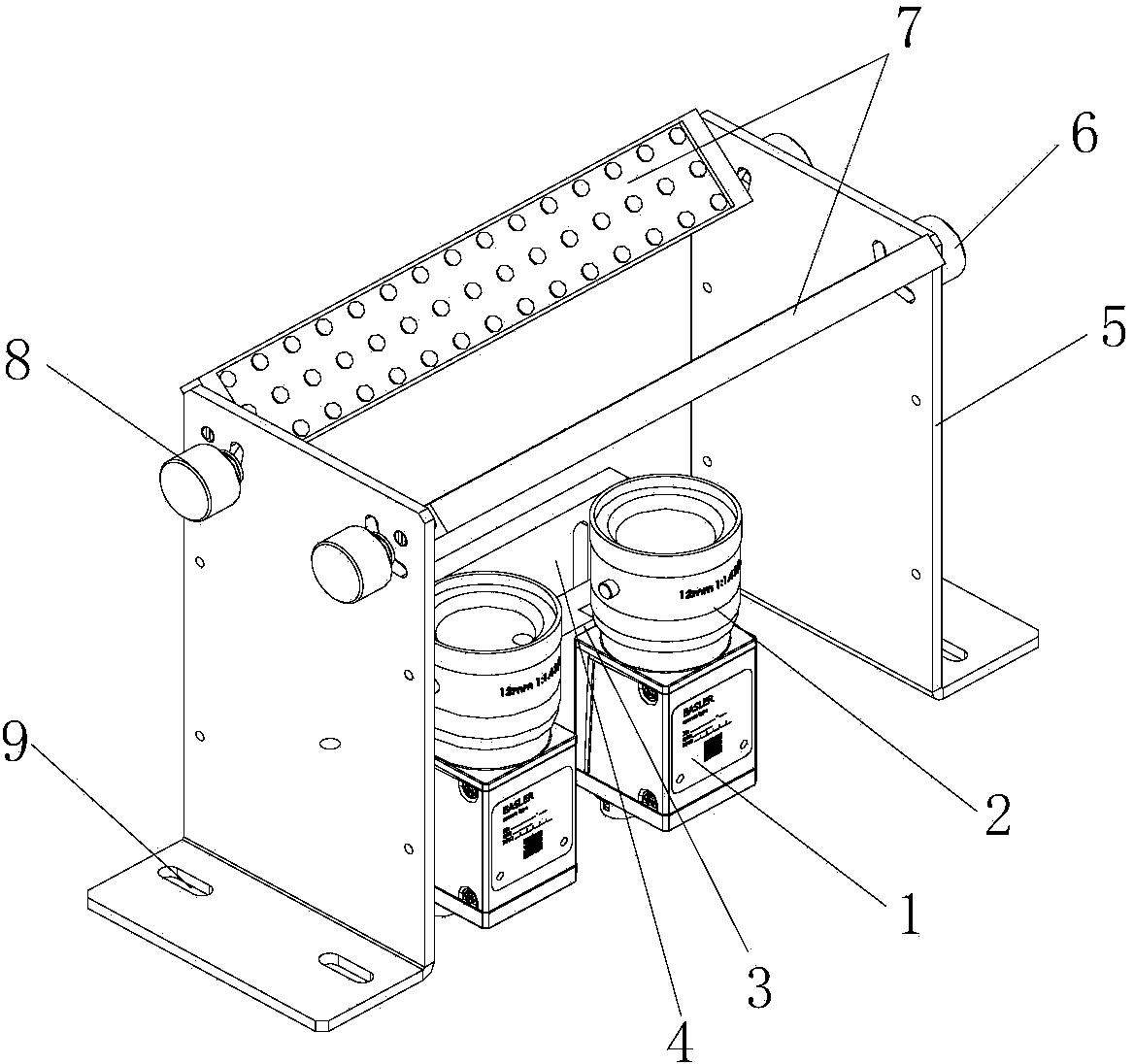
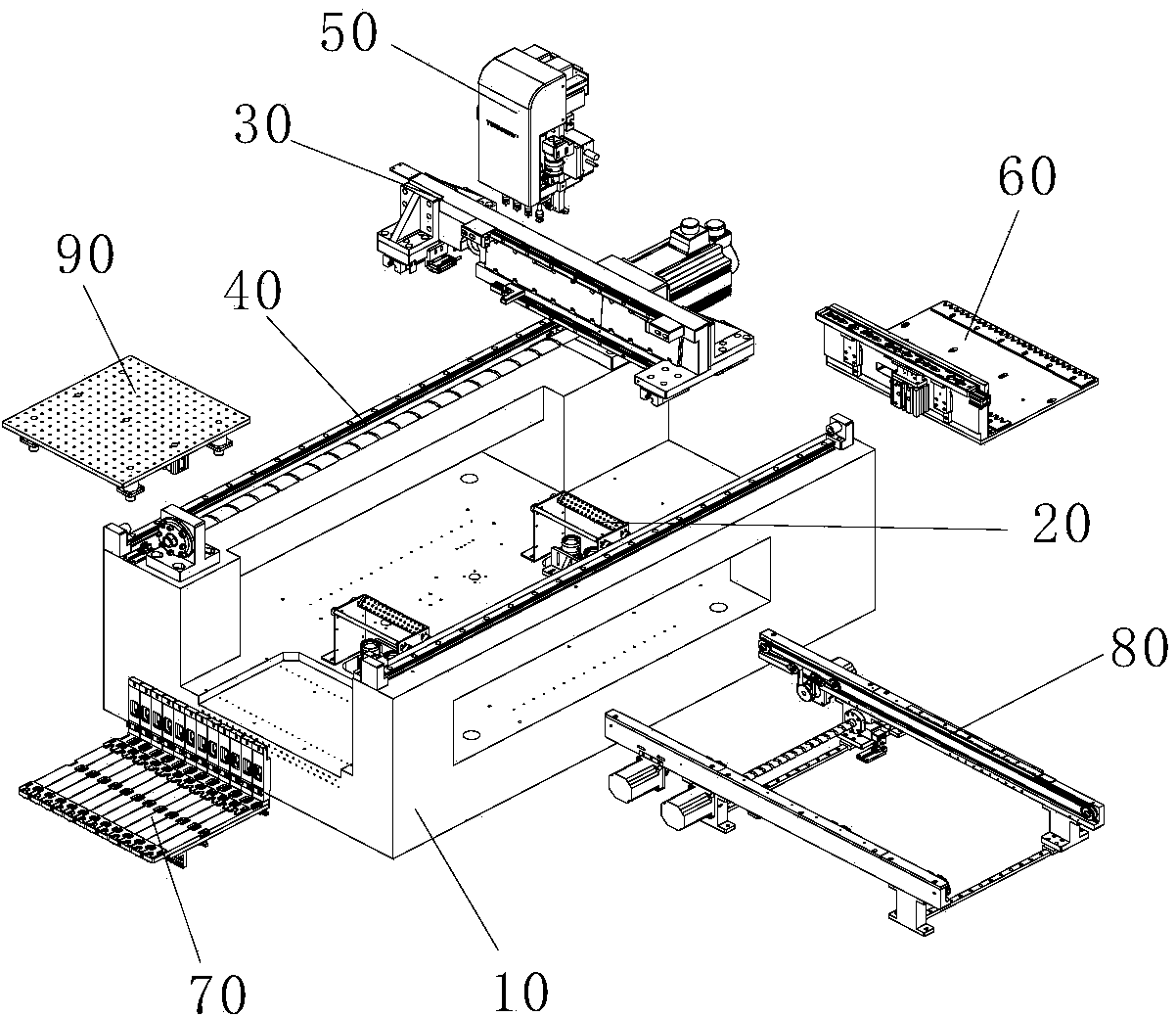
[0026] figure 1 Schematic diagram of the structure of the bottom mirror vision system of the placement machine provided by the embodiment of the present invention; figure 2 It is a schematic diagram of an exploded structure of a placement machine provided by an embodiment of the present invention. refer to figure 1 and figure 2 , Mounter bottom mirror vision system 20, including:

[0027] The camera installation base 4 is arranged on the mounter platform 10;

[0028] The camera mounting plate 3 is arranged on the camera mounting base 3 in an adjustable position;

[0029] The camera 1 is arranged on the corresponding camera mounting plate 3 in an adjustable position;

[0030] Two light source mounting bases 5 are arranged on the mounter platform 10, and the two light source mounting bases 5 are arranged opposit...


PUM


Abstract

The invention discloses a chip mounter and a bottom lens visual system thereof. The bottom lens visual system comprises a camera installing base arranged on a chip mounter platform, a camera installing plate arranged on the camera installing base in a position adjustable mode, a camera arranged on the corresponding camera installing plate in a position adjustable mode, two opposite light source installing bases arranged on the chip mounter platform, and two parallel strip light sources rotationally arranged between the two light source installing bases. Two or more cameras can be linearly arranged along the strip light sources, and the cameras are located between the two strip light sources. Each camera corresponds to at least two paster heads, and during shooting, the cameras are located under the middle points of the connecting lines of the corresponding paster heads. The shooting time is shortened, and accordingly the pasting speed of the chip mounter is increased.

Description

technical field [0001] The invention relates to the technical field of placement machines, in particular to a placement machine and a bottom mirror vision system thereof. Background technique [0002] The placement machine is an important equipment in the field of SMT (Surface Mount Technology). With the development of science and technology, the types of electronic components are increasing and the volume is getting smaller and smaller, so the requirements for the placement machine are getting higher and higher. , mainly focusing on speed, accuracy, stability and other aspects. The speed factor is an important performance indicator that determines the placement machine, and is also an important indicator for the placement machine user to choose equipment. The main factors affecting the placement speed of the placement machine can be summed up in two aspects: first, the movement speed of the placement machine in each axis direction; second, the image recognition of the bott...

Claims


Application Information

Patent Timeline
Patent Type & Authority Applications(China)
IPC IPC(8): H05K3/30G03B15/03
Inventor 赵永先杜伟涛曹帆张延忠罗成帅
Owner 泰姆瑞(北京)精密技术有限公司
Why Eureka
Try Eureka