Method of operating turbine engine after flame off

A technology of turbine engine and electric motor, which is applied in the direction of engine starting, engine components, engine control, etc., can solve the problems of turbine engine cost impact and other issues

Inactive Publication Date: 2014-11-26
ANSALDO ENERGIA IP UK LTD
View PDF8 Cites 8 Cited by
  • Summary
  • Abstract
  • Description
  • Claims
  • Application Information

AI Technical Summary

Problems solved by technology

These battery elements have a considerable cost impact on turbine engines

Method used


Image

  • Method of operating turbine engine after flame off
  • Method of operating turbine engine after flame off
  • Method of operating turbine engine after flame off

Examples


Embodiment Construction

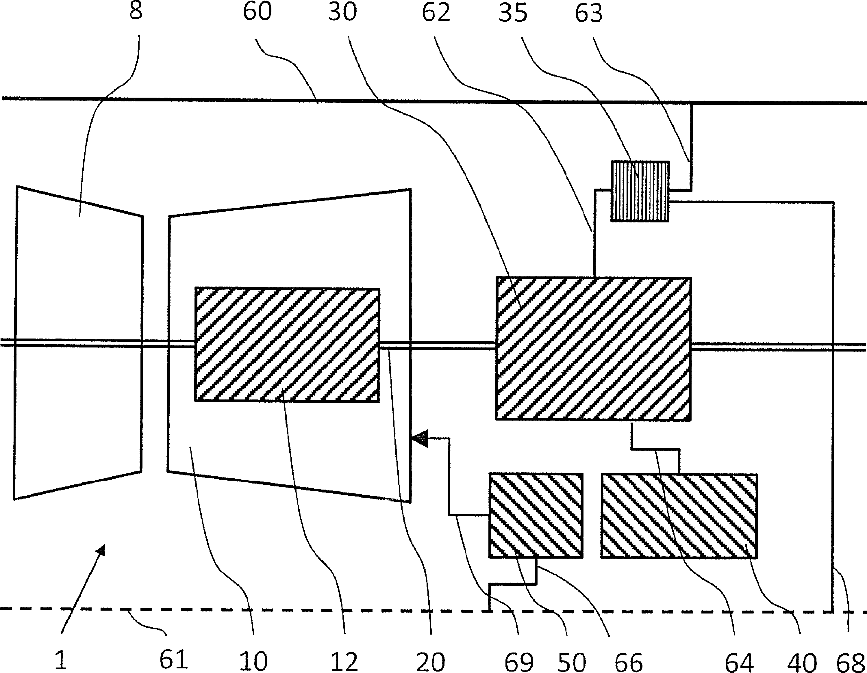
[0099] Exemplarily, the following explanation relies on a large gas turbine engine 1 . However, it should be clear that other simulated turbine systems having different configurations or uses may benefit from the method according to the present invention. It will be understood that various changes and modifications may be made herein by one of ordinary skill in the art without departing from the general spirit and scope of the invention as defined herein.

[0100] Such as figure 1 A typical prior art turbine engine 1 as depicted in may include at least one compressor 8 for compressing an incoming airflow. Compressed air can be delivered to at least one combustor (not shown in the figure), where it is mixed with fuel so that after ignition, the combustion airflow is directed under expansion through a turbine 10 to produce mechanical work via a turbine rotor 12, the turbine rotor 12 The rotor 12 is rotatable about an axis of rotation 20 . The rotor 12 drives the compressor 8 ...


PUM


Abstract

The present invention relates to a method of decelerating a turbine rotor (12) of a turbine engine (1), wherein at least one electric motor (30) is engaged with the turbine rotor (12), wherein a braking system (40), preferably the starting system, is engaged with the at least one electric motor (30), preferably the generator of the turbine engine (1), so as to use the at least one electric motor (30) to apply a negative (braking) torque on the turbine rotor (12). The method is characterized in that, after flame off, the braking system (40) is used for dissipating kinetic energy available in the turbine engine (1) after flame off by means of the at least one electric motor (30).

Description

technical field [0001] The present invention relates generally to turbine systems or engines, and in particular to methods for optimizing turbine rotor deceleration after fuel flow interruption (i.e., after flameout), in particular to reduce overall deceleration time and mechanical and thermomechanical stress. Background technique [0002] The turbine shutdown procedure is an important and regularly performed process that must be performed safely and in a controlled and reliable manner. During engine slow down, the turbine is not productively working; for technical and economic reasons, the resulting dead time should be kept to a minimum. [0003] US2010 / 0275608 A1 provides a method for shutting down a gas turbine engine system comprising the steps of reducing fuel flow to the combustor, reversing the operation of the generator to apply torque to the rotor, and increasing The deceleration of the rotors restricts the flow of air into the gas turbine engine system. For this...

Claims


Application Information

Patent Timeline
Patent Type & Authority Applications(China)
IPC IPC(8): F01D21/14F01D21/02F01D21/00F01D19/00
CPCF05B2260/85F01D21/02F01D21/003F01D21/14F05B2260/90F05B2270/304F01D19/00F01D21/00F01D15/10F01D21/006F02C7/275F05D2220/31F05D2220/32F02C9/48
Inventor K.多伊贝林C.M.罗布森M.吉乌斯蒂
Owner ANSALDO ENERGIA IP UK LTD
Why Eureka
Try Eureka