Water collection cup with alarm device and automatic control of water level
What is Al technical title?
Al technical title is built by PatSnap Al team. It summarizes the technical point description of the patent document.
A technology of water level height and alarm device, applied in the field of water collecting cups, can solve the problem of backflow into the breathing circuit, even the patient, affecting the treatment of the patient, etc.
Active Publication Date: 2016-03-16
袁董瑶
View PDF6 Cites 0 Cited by
Summary
Abstract
Description
Claims
Application Information
AI Technical Summary
This helps you quickly interpret patents by identifying the three key elements:
Problems solved by technology
Method used
Benefits of technology
Problems solved by technology
[0002] Ventilators are currently widely used in the process of rescuing and treating patients in hospitals. When using ventilators, in order to prevent the patient’s airway from drying out, humidification is required. The working principle of humidification is to use a humidification device to heat the water to a certain extent. , to generate a certain amount of water vapor, through the breathing tube, along with the air supply of the ventilator, it enters the patient's airway together to achieve the effect of heating and humidifying. While humidifying the patient, it also causes A large amount of condensed water, for the treatment of condensed water, at present, a water collection cup is added to the ventilator pipeline to collect the condensed water, but the condensed water in the water collection cup needs to be continuously observed by the nurse. Dumping, if the nurse’s supervision is not in place, it is not dumped in time, or the water collection cup is turned over, it is very easy to cause the condensed water to flow back into the breathing circuit or even the patient’s airway, thus affecting the treatment of the patient
Method used
Image
Click on the blue label to locate the original text in one second.
Reading with bidirectional positioning of images and text.
Examples
Embodiment Construction
[0011] The present invention will be further described below in conjunction with accompanying drawing and embodiment:
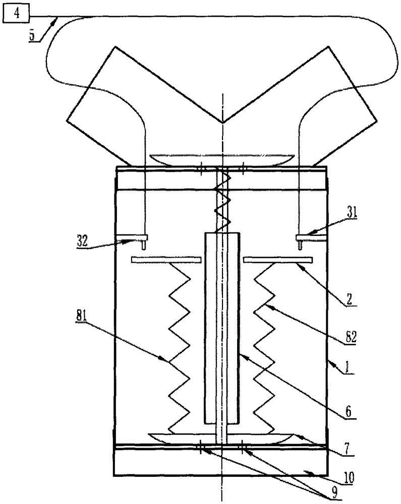
[0012] like figure 1 as shown, figure 1 It is a schematic diagram of a water-collecting cup with an alarm device and automatic control of the water level, including a water-collecting cup body (1), and on the upper 1 / 5 of the water-collecting cup body (1), a limit stop with a waterproof and insulating outer package is installed Microswitches (31, 32), the limit microswitches (31, 32) with waterproof insulation outer packaging are connected with the ventilator alarm part (4) with wires (5), and the upper and lower parts of the water collecting cup body (1) are installed There is a drain plug (7), the drain plug (7) is connected to the floating plate (2) with springs (81, 82), the bottom of the upper water collection cup body is provided with a drainage hole (9), and the lower floor water collection cup body (10) is directly placed on the On the upper water c...
PUM
Abstract
The invention discloses a water collecting cup which is provided with an alarm device and can be used for automatically controlling the water level. The water collecting cup comprises a water collecting cup body of a breathing machine, wherein a limiting microswitch is installed on the upper portion in the main cup body of the water collecting cup body, insulating waterproof materials are arranged outside the limiting microswitch in a packed mode, the limiting switch is connected to the alarm device of the breathing machine, a floating plate large in buoyancy is installed in the water collecting cup body, the floating plate is connected with a drainage plug through a spring, the water collecting cup body is divided into an upper layer cup body and a lower layer cup body, drainage holes are formed in the bottom in the upper layer cup body, the drainage plug is installed at the bottom of the upper layer cup body, the upper layer water collecting cup body is directly sleeved with the lower layer water collecting cup body, and the upper layer water collecting cup body and the lower layer water collecting cup body can be independently separated from each other. The water collecting cup with the alarm device has the advantages that on the one hand, when the water level reaches a certain height or the water collecting cup is inclined, the floating plate ascends along with the water level, the alarm device of the breathing machine is connected when the floating plate makes contact with and triggers the limiting microswitch, and sound and light alarms are given; on the other hand, the spring connected with the floating plate can pull up the plug at the bottom of the upper layer water collecting cup body so that a small part of water can automatically flow into the lower layer water collecting cup body through the drainage holes in the bottom of the upper layer water collecting cup body, the floating plates descends, the plug sinks, the drainages holes of the upper layer water collecting cup body are blocked, and the alarms disappear; but when condensate water ascends to make the floating plate make contact with and trigger the limiting microswitch again, the actions are repeated again, and in the repetition way, a nurse can be warned to pour accumulated water in the water collecting cup in time and the position of the water collecting cup is adjusted; besides, part of accumulated water in the upper layer water collecting cup body can automatically flow to the lower layer water collecting cup body when a nurse is busy with rescuing a patient and has no time to handle the water collecting cup, and a poor influence factor in use of the breathing machine is avoided; in addition, the lower water collecting cup body can be directly taken down quite conveniently, and the condensate water in the lower layer water collecting cup body can be conveniently extracted to be used for medical tests.
Description
technical field [0001] The invention relates to a ventilator used in a hospital, in particular to a water collecting cup of the ventilator. Background technique [0002] Ventilators are currently widely used in the process of rescuing and treating patients in hospitals. When using ventilators, in order to prevent the patient’s airway from drying out, humidification is required. The working principle of humidification is to use a humidification device to heat the water to a certain extent. , to generate a certain amount of water vapor, through the breathing tube, along with the air supply of the ventilator, it enters the patient's airway together to achieve the effect of heating and humidifying. While humidifying the patient, it also causes A large amount of condensed water, for the treatment of condensed water, at present, a water collection cup is added to the ventilator pipeline to collect the condensed water, but the condensed water in the water collection cup needs to be...
Claims
Application Information
Patent Timeline
Application Date:The date an application was filed.
Publication Date:The date a patent or application was officially published.
First Publication Date:The earliest publication date of a patent with the same application number.
Issue Date:Publication date of the patent grant document.
PCT Entry Date:The Entry date of PCT National Phase.
Estimated Expiry Date:The statutory expiry date of a patent right according to the Patent Law, and it is the longest term of protection that the patent right can achieve without the termination of the patent right due to other reasons(Term extension factor has been taken into account ).
Invalid Date:Actual expiry date is based on effective date or publication date of legal transaction data of invalid patent.