
Air removal device for water tunnels

A gas device and water tunnel technology, which is applied in the field of devices for reducing air content in water and water tunnel degassing devices, can solve the problems of unsuitable water tunnel degassing, inappropriate, low efficiency, etc., to avoid the hazards of cavitation and cavitation Effect

Inactive Publication Date: 2014-12-03
NORTHWESTERN POLYTECHNICAL UNIV
View PDF4 Cites 4 Cited by
  • Summary
  • Abstract
  • Description
  • Claims
  • Application Information

AI Technical Summary

Problems solved by technology

Although the gravity-centrifugal two-stage degassing device is good for oil degassing, it is not ideal for water degassing, and the whole system is relatively large, so it is not suitable for degassing existing water tunnels
Although the degassing mechanism of the forced air bubble remover and vacuum degassing device is simple, there is no corresponding theoretical calculation method to guide the structural design, and the capacity is too small, the efficiency is low, and it is not suitable for water tunnel degassing
However, because the viscosity of oil is higher than that of water, the above-mentioned degassing devices are not suitable for reducing the gas content in water.
In addition, the design of these separators is limited to traditional experience and generalized methods, and only qualitative analysis can be made on their separation performance. The reason is that the gas-liquid two-phase flow is a complex multiphase flow with deformable interfaces and Compressible gas phase, meanwhile, multiphase flow theory itself is not perfect due to the complexity of turbulent flow
In the water tunnel experiment, if the gas content in the water is high, it will affect the accuracy of the water tunnel experiment and lead to cavitation and cavitation.

Method used


Image

  • Air removal device for water tunnels
  • Air removal device for water tunnels
  • Air removal device for water tunnels

Examples


Embodiment Construction

[0021] This embodiment is a water tunnel degassing device.

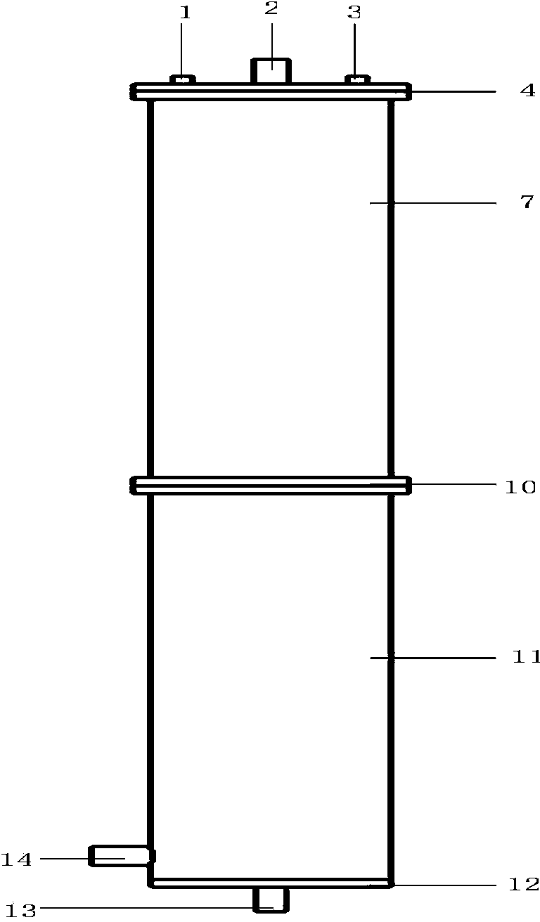
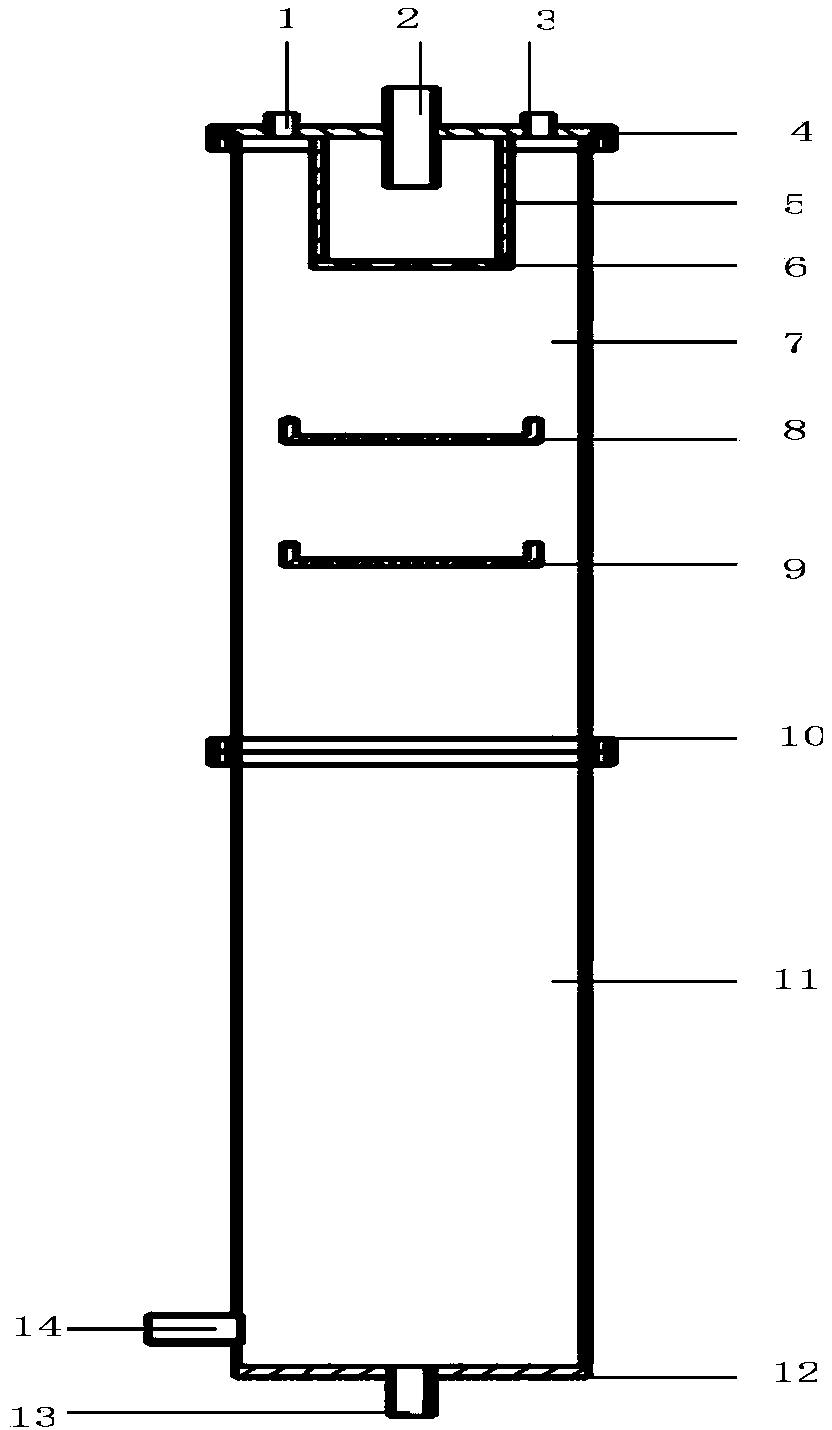
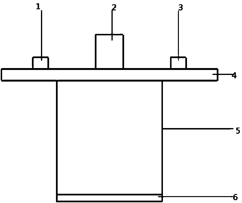
[0022] refer to Figure 1 to Figure 5 , the water tunnel degassing device in this embodiment consists of an upper barrel body 7, a lower body 11, a cover plate 4, a sleeve 5, a primary orifice plate 6, a secondary orifice plate 8, a third orifice plate 9, an inlet pipe 2, an outlet Water pipe 14, vacuum pipe 3, cleaning pipe 1, discharge pipe 13, chassis 12, and flange plate 10 form. The upper barrel body 7 and the lower barrel body 11 are fixedly connected by a flange 10, the cover plate 4 is installed on the upper end of the upper barrel body 7, the cover plate 4 and the upper barrel body 7 are fixedly connected by a flange plate and bolts, and the cover plate 4 In the upper middle part, there is a water inlet pipe 2 communicating with the sleeve 5 in the upper barrel body 7. The sleeve 5 is installed in the middle part under the cover plate 4. The sleeve 5 is fixedly connected with the cover plate 4. The primary ...


PUM


Abstract

The invention discloses an air removal device for water tunnels, which increases the flow velocity of water and reduces the pressure of water through gravity settling and vacuumizing and by using an orifice air removal generator, so that air dissolved in the water is expanded into bubbles from air cores at low pressure, and the bubbles dissolved in the water quickly emerge from the water, thereby achieving air-liquid separation. Upper and lower barrel bodies are connected by a flange plate, a cover plate is fixedly connected with the upper barrel body, the cover plate is provided with a water inlet pipe communicated with a sleeve, the sleeve is fixed at the middle position of the downside of the cover plate, a first-level orifice is arranged at the bottom of the sleeve, a second-level orifice and a three-level orifice are fixed below the sleeve, a cleaning tube and a vacuumizing tube are located on both sides of the water inlet pipe and communicated with the upper barrel body, a discharge pipe is arranged on a chassis, and a water outlet pipe is located on one side of the lower barrel body. The air removal device can quickly carry out air removal on a large amount of experimental water for water tunnels, thereby avoiding cavitation and erosion hazards caused by air contained in the water in the process of experiments. The air removal device can be applied to the removal of air contained in oil and the air removal of water for air conditioning circulation.

Description

technical field [0001] The invention relates to a device for reducing the gas content in water, in particular to a water tunnel degassing device. The invention belongs to the technical field of fluid degassing. Background technique [0002] At present, there are several types of degassing devices used to remove gas contained in petroleum: gravity-centrifugal two-stage degassing device, forced air bubble remover, and vacuum degassing device. [0003] In the existing published technical literature "Degassing System Design and Simulation Test of High-density Drilling Fluid" (Petroleum Machinery, Issue 10, Volume 38, 2010), the high-density drilling fluid used in high-pressure gas wells is difficult to degas after being attacked by gas. In order to solve the problem, an indoor simulated secondary degassing test bench was designed; in the literature "Research on Hydraulic Oil Air Bubble Remover" (Machinery Manufacturing, Issue 11, Volume 40, 2002), the harmfulness of air bubbles...

Claims


Application Information

Patent Timeline
IPC IPC(8): B01D19/00
Inventor 邓飞王科燕丁文俊
Owner NORTHWESTERN POLYTECHNICAL UNIV
Learn More