Normal-pressure, pressurizing and high-pressure die locking loop of two-plate hydraulic injection molding machine

An injection molding machine and hydraulic technology, applied in the improvement field of hydraulic high-pressure mold clamping circuit, can solve the problems of reduced system reliability, poor impact resistance performance and process stability, increased power consumption, etc., to achieve fast response speed, large driving force, The effect of structural simplification

Active Publication Date: 2014-12-03
山东胜沃塑料机械科技有限公司
View PDF5 Cites 6 Cited by
  • Summary
  • Abstract
  • Description
  • Claims
  • Application Information

AI Technical Summary

Problems solved by technology

But there are also the following disadvantages: first, the structure is complex, the operation process is cumbersome, and the action response speed is difficult to improve; second, the diameter of the clamping hydraulic cylinder is often limited by the size, resulting in insufficient clamping force. In order to improve the clamping force, the current method is Increase the oil pressure of the hydraulic system, which increases power consumption; third, it does not have the function of normal pressure mold clamping; fourth, when high pressure mold clamping, power matching is difficult t...

Method used


Image

  • Normal-pressure, pressurizing and high-pressure die locking loop of two-plate hydraulic injection molding machine

Examples


Embodiment

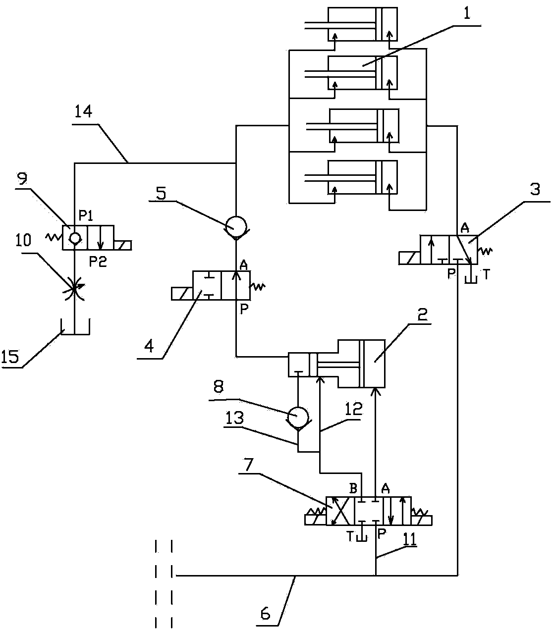
[0013] figure 1 An example of the invention is given. refer to figure 1 Make the invention. The two-platen hydraulic injection molding machine has normal pressure, pressurized and high-pressure clamping circuits, including clamping hydraulic cylinder 1, boosted hydraulic cylinder 2, two-position three-way reversing valve 3, and two-position two-way reversing valve of the clamping oil circuit. 4 and clamping oil circuit check valve 5, four clamping hydraulic cylinders 1 are connected in parallel, the oil inlet P of the two-position three-way reversing valve 3 is connected to the pressure oil pipe 6 connected to the high-pressure oil pump station, and the two-position three-way reversing The upper oil port A of valve 3 communicates with the rodless cavity of four clamping hydraulic cylinders 1 through corresponding oil pipes; The reversing valve 4 and the mold clamping oil circuit check valve 5 communicate with the rod chambers of the four mold clamping hydraulic cylinders 1 ...


PUM


Abstract

The invention discloses a normal-pressure, pressurizing and high-pressure die locking loop of a two-plate hydraulic injection molding machine. The normal-pressure, pressurizing and high-pressure die locking loop of the two-plate hydraulic injection molding machine comprises a die locking hydraulic cylinder, a pressurizing hydraulic cylinder, a two-position three-way reversing valve, a die locking oil line two-position three-way reversing valve and a die locking oil line one-way valve. The normal-pressure, pressurizing and high-pressure die locking loop of the two-plate hydraulic injection molding machine is characterized in that a pressure oil pipe is connected with a pressure side oil hole P of a three-position four-way reversing valve through a first branch pressure oil pipe; a right end upper side oil hole A of the three-position four-way reversing valve is connected with an oil hole of a rodless cavity of a large oil cylinder of the pressurizing hydraulic cylinder; a left end upper side oil hole B of the three-position four-way reversing valve is communicated with a rod cavity of a small oil cylinder of the pressurizing hydraulic cylinder through a communication oil pipe; meanwhile, the left end upper side oil hole B of the three-position four-way reversing valve is also communicated with a rodless cavity of the small oil cylinder of the pressurizing hydraulic cylinder through a second branch oil pipe. The normal-pressure, pressurizing and high-pressure die locking loop of the two-plate hydraulic injection molding machine is simple in structure and easy to operate, has two functions of locking a die under the normal pressure and locking the die under the high pressure, and is capable of locking the die, reducing the impact buffer on a contact surface of the die by virtue of locking the die under the normal pressure, and meeting the requirement of initial stability of the die locking process.

Description

[0001] technical field [0002] The invention relates to an improvement of a hydraulic high-pressure mold-clamping circuit of an injection molding machine, in particular to a normal-pressure, pressurized and high-pressure mold-clamping circuit of a two-platen hydraulic injection molding machine. Background technique [0003] The injection molding machine is the main equipment for injection molding. The hydraulic high-pressure clamping circuit is the key circuit system of the injection molding machine, which effectively ensures the locking of the mold. At present, although there are multiple reports on the hydraulic high-pressure mold clamping circuit used in the two-platen injection molding machine, such as the disclosed "two templates with large opening distance full hydraulic clamping injection molding machine" disclosed by the Chinese Patent Publication No. CN101758605A and the disclosed "large Clamping oil circuit system of two-platen injection molding machine", its stru...

Claims


Application Information

Patent Timeline
IPC IPC(8): B29C45/67
CPCB29C45/67
Inventor 刘军营田浩张开国石昌连
Owner 山东胜沃塑料机械科技有限公司
Why Eureka
Try Eureka