Automobile fuel tank

A technology for fuel tanks and automobiles, which is applied to vehicle components, the arrangement combined with the fuel supply of internal combustion engines, power plants, etc., and can solve the problems of fatigue cracking at the connection between the upper tank and the lower tank, vibration and instability of the fuel pump and dump valve , Stress dispersion at the joint, local stress and other issues, to achieve the effect of compact structure, high toughness, and easy processing and forming

Active Publication Date: 2014-12-03
重庆双五汽车零部件有限公司
View PDF8 Cites 13 Cited by
  • Summary
  • Abstract
  • Description
  • Claims
  • Application Information

AI Technical Summary

Problems solved by technology

However, in order to supplement the space at the fuel pump with air and make the fuel discharge smoothly, the existing metal fuel tanks have a full structure; however, when the fuel pump and the dump valve are installed on the fuel tank, the fuel pump and the The dump valve protrudes from the surface of the fuel tank, which not only takes up space in the car, but also makes the fuel pump and the dump valve easy to vibrate and unstable
In addition, the metal fuel tank is generally mainly composed of the upper tank and the lower tank. When the motor drive, fuel pump, dump valve and other hydraulic components are installed on the fuel tank, the upper and lower parts of the fuel tank will be shaken due to vibration. It leads to stress dispersion and high local stress at the connection, which leads to fatigue cracks at the connection between the upper tank and the lower tank, and the cracks spread to the surroundings, making the connection between the upper and lower parts of the tank unstable, and finally weakening the sealing of the fuel tank

Method used


Image

  • Automobile fuel tank
  • Automobile fuel tank
  • Automobile fuel tank

Examples


Embodiment

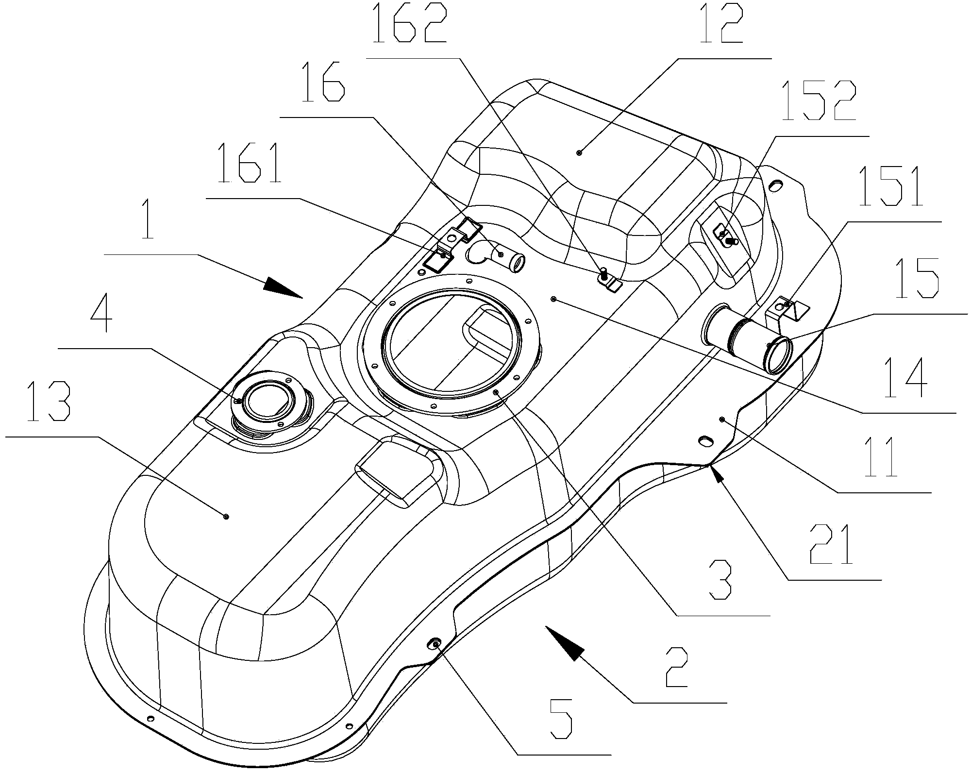
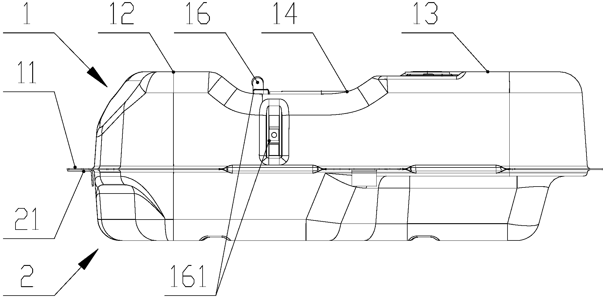
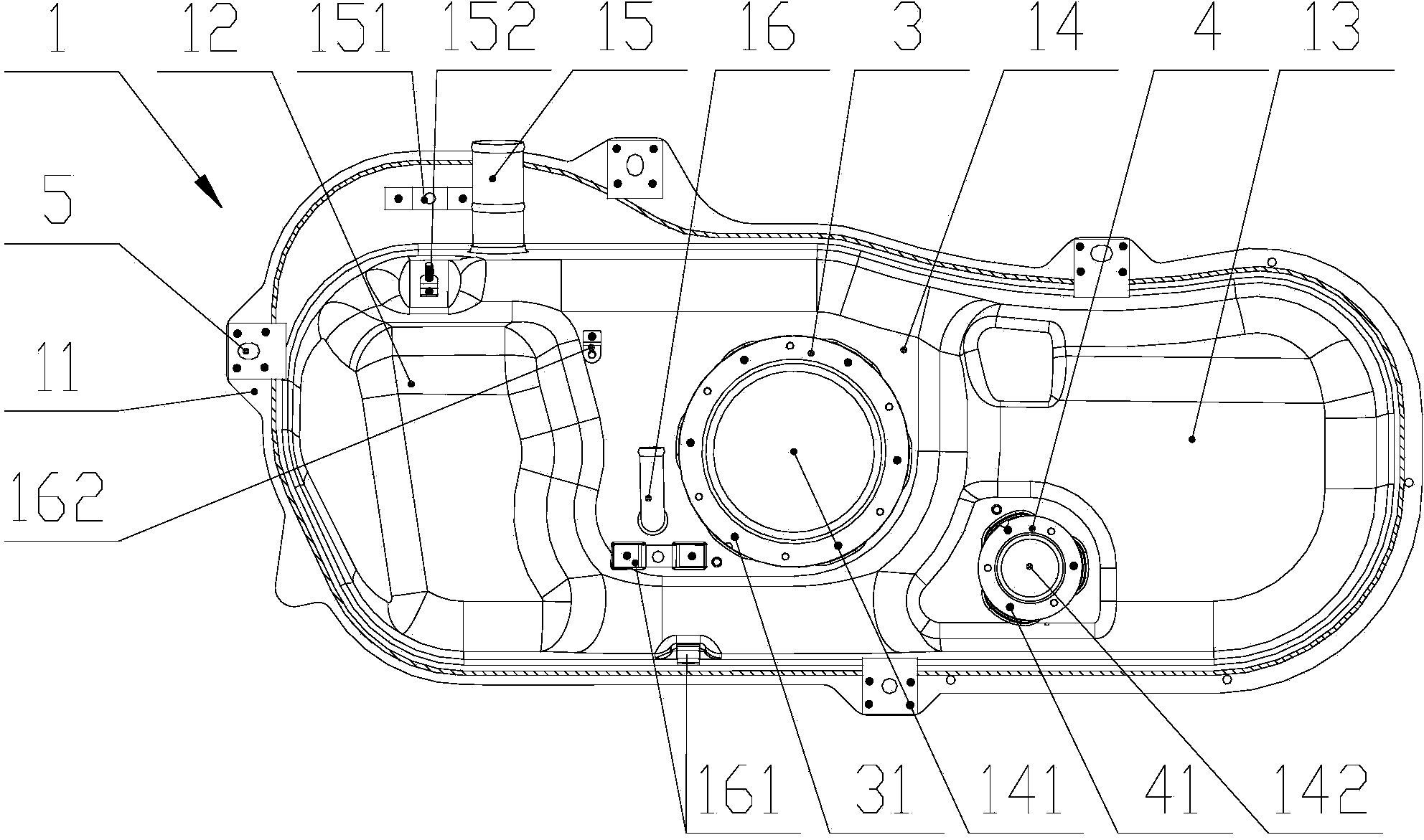
[0035] The upper box 1 is made of cold-rolled steel plate DC04 with a thickness of 0.8mm, and the lower box 2 is made of cold-rolled steel plate DC04 with a thickness of 1.0mm; the height of the upper box 1 is 150mm, and the height of the lower box 2 is 110mm; The transition fillet radius between the sides of the upper box 1 is 85mm, the transition fillet radius between the top surface and the side of the upper box 1 is 25mm; the transition fillet between the sides of the lower box 2 The radius is 85mm, and the transition fillet radius between the bottom surface and the side of the lower box body 2 is 30mm; the transition fillet between the upper box body 1 and the upper box ring edge 11 is 5mm; the lower box body 2 and the lower box ring The transition fillet between the sides 21 is 5 mm; ensure that the upper box body 1 and the lower box body 2 cannot have defects such as cracking and wrinkling during the molding process, and the material thinning rate is greater than or equa...


PUM


Abstract

The invention discloses an automobile fuel tank which is low in cost. An upper tank body and a lower tank body are connected firmly and stably. The occupied vehicle interior space is small after a fuel pump and a turning-over valve are installed. The fuel tank comprises the upper tank body and the lower tank body arranged on the lower side of the upper tank body. The upper tank body and the lower tank body are made of metal materials respectively. An upper tank-closing ring edge is arranged on the portion, along the edge of the lower side, of the upper tank body. A lower tank-closing ring edge is arranged on the portion, along the edge of the upper side, of the upper tank body. The upper tank-closing ring edge and the lower tank-closing ring edge are matched and welded together in a rolling mode. The upper tank body is a concave casing with the front end and the rear end being protruding faces and the middle portion being a sunken face. The sunken face of the upper tank body is provided with a fuel pump installing flange and a turning-over valve installing flange. The upper tank body is further provided with an oil filling pipe and a ventilation pipe. The cost of the fuel tank is far smaller than that of a plastic fuel tank. The upper tank body and the lower tank body are connected firmly and stably, and influence of vibration is small; due to the sunken face, the tail portion of the installed fuel pump and the tail portion of the turning-over valve are prevented from protruding or protruding excessively.

Description

technical field [0001] The invention belongs to the field of automobile fuel systems, and in particular relates to an automobile fuel tank. Background technique [0002] The automobile fuel tank is a device for storing fuel in the automobile and is an important part of the automobile fuel system. Traditional plastic fuel tanks are popular in the world's automobile industry due to their light weight, strong anti-corrosion ability, easy shape, high safety, and long service life. However, the manufacturing cost of plastic fuel tanks is high, and it is difficult to meet the requirements of zero penetration of the fuel system promulgated by California, and plastic fuel tanks are more harmful to the environment during the raw material manufacturing process and waste disposal process. [0003] With the improvement of sheet metal forming technology and metal surface anti-corrosion treatment technology, the manufacturing technology of metal fuel tanks is also improving. More and mor...

Claims


Application Information

Patent Timeline
Patent Type & Authority Applications(China)
IPC IPC(8): B60K15/073
Inventor 明安均
Owner 重庆双五汽车零部件有限公司
Why Eureka
Try Eureka