A flexible umbrella-shaped support bolt and its method for supporting soil slopes

An anchor rod and umbrella-shaped technology is applied in the field of geotechnical engineering slope protection, which can solve the problems of unreliable connection and fixation of the steel anchor rod and the flexible net, reducing the service life of the slope protection, and the separation of the anchor rod and the protective flexible net, etc. The anchoring effect is firm and reliable, the construction quality is easy to ensure, and the anchoring effect is reliable.

An anchor rod and umbrella-shaped technology is applied in the field of geotechnical engineering slope protection, which can solve the problems of unreliable connection and fixation of the steel anchor rod and the flexible net, reducing the service life of the slope protection, and the separation of the anchor rod and the protective flexible net, etc. The anchoring effect is firm and reliable, the construction quality is easy to ensure, and the anchoring effect is reliable.

CN104179178BActive Publication Date: 2015-12-09NANCHANG INST OF TECH

Image

  • A flexible umbrella-shaped support bolt and its method for supporting soil slopes
  • A flexible umbrella-shaped support bolt and its method for supporting soil slopes
  • A flexible umbrella-shaped support bolt and its method for supporting soil slopes

Examples


Embodiment 1

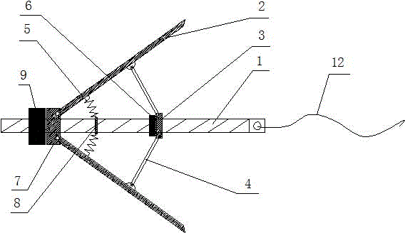
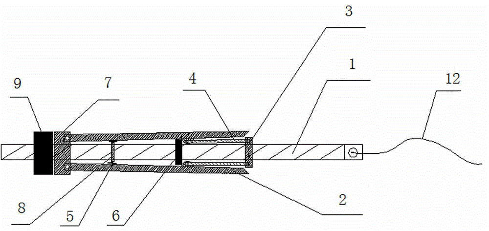
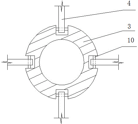
[0023] Example 1 Such as Figure 1-4 Shown: a flexible umbrella-shaped support anchor, the end collar 9 and the end ring connector 7 are fixedly installed at the end of the circular anchor 1, and the spring ring connector is fixedly installed at the middle of the circular anchor 1 8 and the middle collar 6, on the circular anchor 1, next to the movable sleeve lower annular connector 3 on the right side of the middle collar 6; the resistance parachute surrounding the circular anchor 1 includes uniformly distributed reaction plates 2, pull 4. The compression spring 5, the end of the counter force plate 2 is hinged with the end ring connector 7 through the rotating shaft 11, one end of the pull rod 4 is hinged with the lower ring connector 3 through the pin shaft 10, and the other end of the pull rod 4 is connected with the mandrel. The middle part of the reaction force plate 2 is hinged, one end of the compression spring 5 is hinged with the spring ring connector 8 through the...

Embodiment 2

[0025] Example 2 Such as Figure 1-5 Shown: adopt the method for the flexible umbrella-shaped support bolt support soil layer slope described in embodiment 1, comprise:

[0026] 1. at first carry out drilling with the drilling equipment at the design position of the anchor rod in the soil body 16 of the slope, and the diameter of the drilled hole will be more than 3cm larger than the diameter of the fixed end collar 9;

[0027] ② After the drilling depth reaches the design requirements, clean the hole and use grouting equipment to grout at the bottom of the anchor hole. The grouting depth should exceed 30cm from the end of the flexible umbrella support anchor. Anti-rust treatment for support bolts;

[0028] ③Put the flexible cable 12 and the right end of the circular anchor 1 into the auxiliary steel pipe whose diameter is larger than the circular anchor 1 and smaller than the lower annular connector 3;

[0029] ④The auxiliary steel pipe withstands the lower annular connec...


PUM


Abstract

The invention relates to a flexible umbrella supporting anchor bolt and a method for supporting a soil slope thereby. An end ring and an end circular connector are fixedly disposed at one end of a round anchor bolt. A spring circular connector and a middle ring are fixedly disposed in the middle of the round anchor bolt. A lower circular connector adjacent to the right side of the middle ring movably sleeves the round anchor bolt. A drag umbrella surrounding the round anchor bolt comprises reacting plates evenly arranged, pull rods and compression springs. One end of a flexible pull rope is fixed to a round hole arranged in the other end of the round anchor bolt. More than one flexible umbrella supporting anchor bolt is connected with a soil high slope protective structure, composed of a geogrid mesh, a vegetation protective layer and a retaining wall, through the flexible pull ropes, and a whole for firmly and reliably anchoring and protecting the soil high slope is formed. The umbrella reacting plates are connected with the protective structural mesh through the flexible pull rope, anchoring force is greatly higher than that of a traditional anchor bolt, anchoring effect is more reliable, and engineering cost can be decreased by 50-60%.

Description

technical field [0001] The invention relates to the field of geotechnical engineering slope protection, in particular to a flexible umbrella-shaped support bolt and a method for supporting soil layer slopes. Background technique [0002] Since 1912, Germany was the first to use bolts to support underground roadways. Bolts have been widely used in civil engineering because of their simple structure, convenient construction, low cost and strong adaptability to engineering. The anchors can be divided into soil anchors and rock anchors according to their different reinforcement objects. The soil anchors and rock anchors are somewhat similar in name, but their purposes and functions are very different. The rock bolt is mainly through the suspension effect of the anchor rod, the effect of the composite beam, the effect of the composite arch, the effect of reducing the span, and the reinforcement effect to stabilize the broken and weak rock formation itself. The soil anchor is mai...

Claims


Application Information

Patent Timeline
09 Dec 2015
Publication
CN104179178B
IPC
E02D5/74; E02D17/20
Inventors
张鸿; 吴文清