Multi-wing centrifugal fan

A centrifugal fan and air inlet ring technology, applied in mechanical equipment, machines/engines, liquid fuel engines, etc., can solve the problems of failure to effectively reduce the flow loss at the impeller inlet, and can not effectively reduce the flow loss at the impeller inlet, so as to reduce the intake Effect of air attack angle, reduction of flow loss, and increase of air volume

Inactive Publication Date: 2014-12-03
GUANGDONG HISENSE HOME APPLIANCES CO LTD
View PDF7 Cites 17 Cited by
  • Summary
  • Abstract
  • Description
  • Claims
  • Application Information

AI Technical Summary

Problems solved by technology

[0004] Chinese patent application number 201220696030.7 discloses a fan, including a volute, the volute is provided with an air inlet and an air outlet, wherein the air outlet is provided with an insect-proof net for the fan, and the insect-proof net is provided mainly to prevent insects from entering the volute and affecting the service life of the fan , but it cannot effectively reduce the flow loss at the impeller inlet
Another example is that Chinese patent application number 201310217396.0 discloses a centrifugal fan. A shroud is arranged at the air inlet of the fan. The end of the shroud extends into the fan wheel cavity. The shroud is mainly for introducing outside air into the fan wheel cavity. In order to increase the air volume and reduce the noise, but it also failed to effectively reduce the flow loss at the impeller inlet

Method used


Image

  • Multi-wing centrifugal fan
  • Multi-wing centrifugal fan
  • Multi-wing centrifugal fan

Examples


Embodiment 1

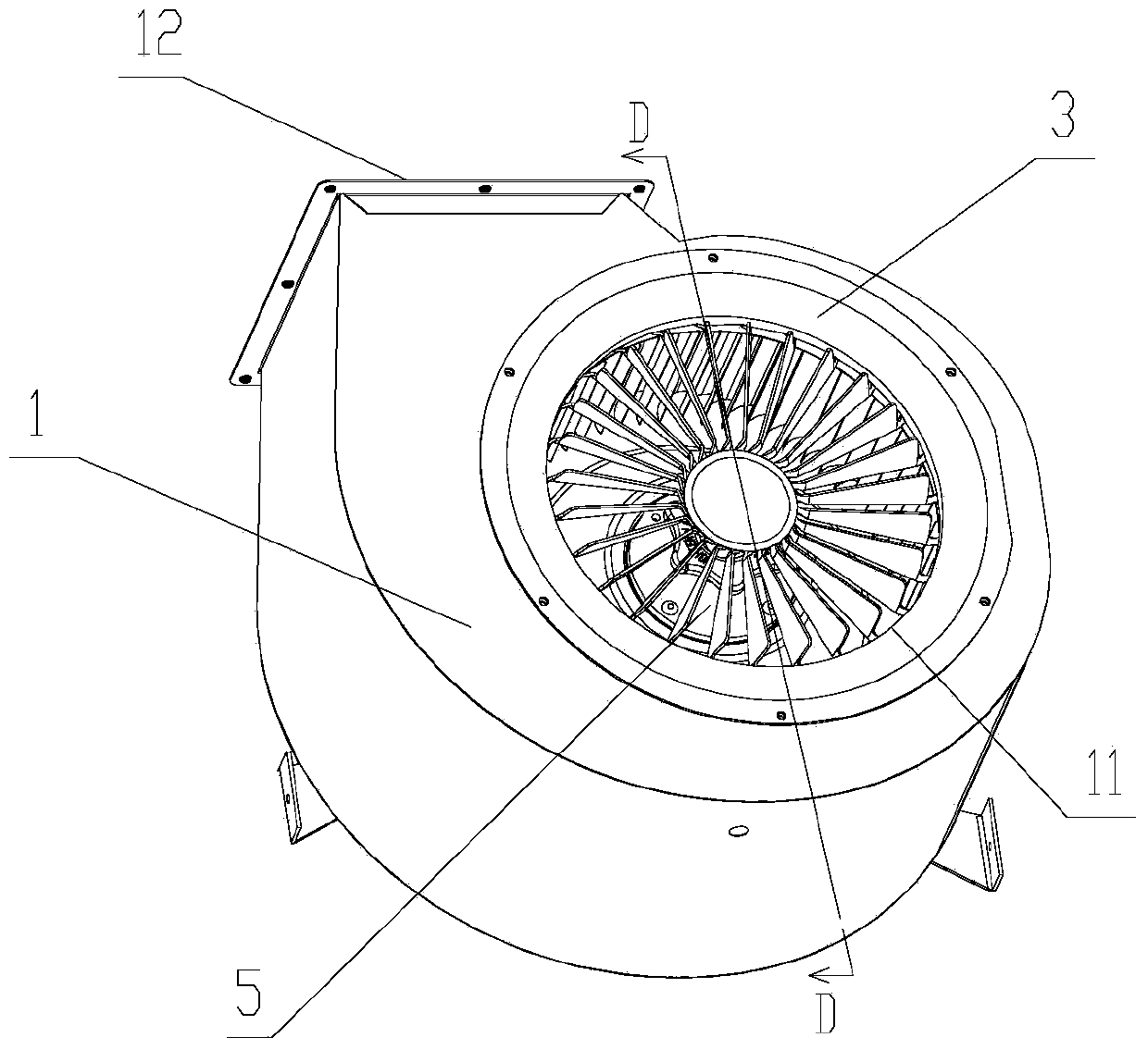
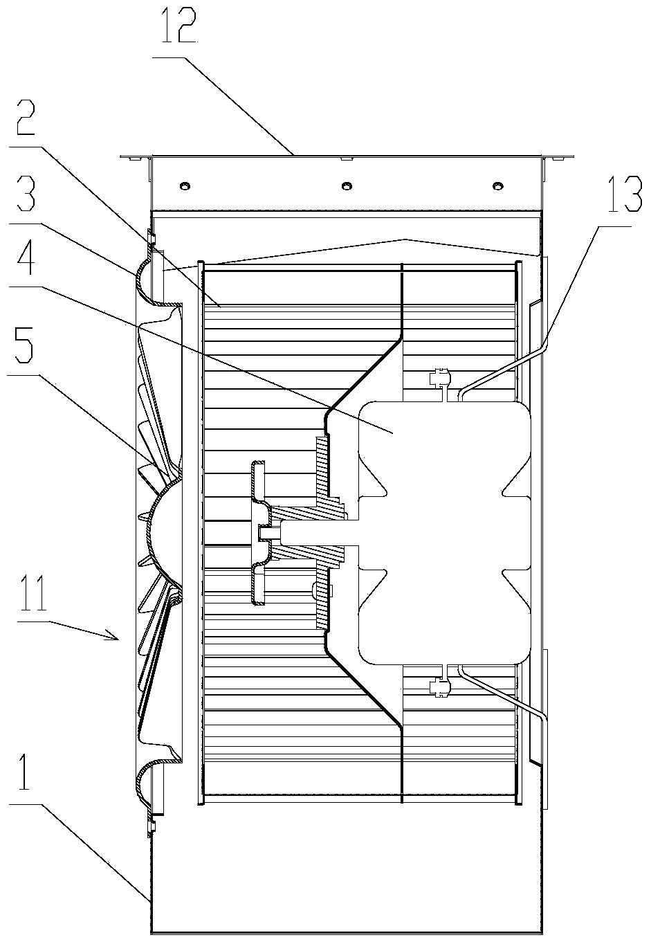
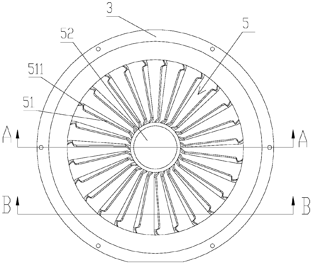
[0028] The multi-blade centrifugal fan of the present invention is as Figures 1 to 5 As shown, it includes a volute 1, an impeller 2, an air inlet ring 3, a motor 4 and a vane guide 5, wherein the impeller 2 is installed on the rotating shaft of the motor 4 and placed in the volute 1, and the motor 4 drives the impeller 2 to rotate. The volute 1 is provided with an air inlet channel 11 and an air outlet channel 12, the air inlet ring 3 is installed at the position of the air inlet channel 11 of the volute 1, the vane guide 5 is placed in the air inlet channel 11, and the air inlet ring 3 is set On the periphery of the vane guide 5, the vane guide 5 includes guide vanes 51 and a hub 52, the guide vanes 51 are evenly distributed on the periphery of the hub 52 in a ring shape, the guide vanes 51 are arranged obliquely, and the inclined direction of the guide vanes 51 rotates with the impeller 2 The direction is the same, one end of the guide vane 51 is connected to the hub 52 th...

Embodiment 2

[0033] The multiblade centrifugal blower of the present embodiment is similar to embodiment 1, and its difference is: as Figures 6 to 9 As shown, the outer surface of the above-mentioned wheel hub 52 is a plane, and the wheel hub 52 is provided with several ventilation holes 521 to reduce the end face of the wheel hub 52 blocking air, and the loss of air flow. The periphery of the vane guide 5 is also provided with a connecting ring 4 , the end of the vane 51 of the vane guide 5 away from the hub 52 is connected to the connecting ring 6 through a curved surface connecting body 511. In this embodiment, the vane guide 5 and the connecting ring 6 are integrally formed injection molded parts or sheet metal parts. When the connecting ring 4 is located outside the air inlet ring 3, the screw passes through the connecting ring 6, and the air inlet ring 3 is connected with the volute 1 to realize the fixed installation of the air inlet ring 3 and the vane guide 5. Of course, it can al...


PUM


Abstract

The invention provides a multi-wing centrifugal fan. The multi-wing centrifugal fan comprises a spiral case, an impeller and a motor, wherein the motor is fixed on the spiral case; the impeller is arranged on a rotating shaft of the motor and is placed in the spiral case; the spiral case is provided with an air inlet channel and an air outlet channel; a blade guiding device is arranged in the air inlet channel of the spiral case and comprises guiding blades and a hub; the guiding blades are annularly distributed on the periphery of the hub and are inclined; and the inclined direction of the guiding blades is the same with the rotation direction of the impeller. Because the blade guider is arranged in the air inlet channel of the spiral case, before air flow flows through the guiding blades of the blade guider from the air inlet channel and enters a cavity of the impeller, the guiding blades rotate in advance, the rotation direction of the guiding blades is the same with that of the impeller, the air inlet attract angle of an inlet of the impeller can be reduced, so that the flowing loss of the inlet of the impeller is reduced, and the air volume of the fan is increased.

Description

technical field [0001] The invention relates to a fan, in particular to a multi-blade centrifugal fan, which belongs to the improvement technology of the fan. Background technique [0002] Multi-blade centrifugal fans have the characteristics of large flow coefficient, high pressure coefficient and compact structure, and have been widely used in industrial products. At present, most of the fans in the range hood industry use multi-blade centrifugal fans. [0003] The impeller of the multi-blade centrifugal fan adopts the form of multiple blades and short blades, and adopts the form of forward-leaning blades. The research shows that the use of accelerating blades is beneficial to improve the flow separation in the blades of the multi-blade centrifugal fan. However, in order to realize the accelerated blades, A larger blade inlet airflow angle (usually greater than 60 degrees) and a smaller blade outlet airflow angle (usually less than 30 degrees) are often required. A larger ...

Claims


Application Information

Patent Timeline
Patent Type & Authority Applications(China)
IPC IPC(8): F04D29/44
Inventor 梁之博
Owner GUANGDONG HISENSE HOME APPLIANCES CO LTD
Why Eureka
Try Eureka