Efficient cross-flow wind wheel

A cross-flow wind rotor, high-efficiency technology, applied in the components of the pumping device for elastic fluid, non-variable-capacity pump, noise suppression, etc. weight issues

Pending Publication Date: 2021-05-18
GUANGDONG SUNWILL PRECISING PLASITC CO LTD
View PDF0 Cites 0 Cited by
  • Summary
  • Abstract
  • Description
  • Claims
  • Application Information

AI Technical Summary

Problems solved by technology

[0002] like image 3 As shown, the traditional cross-flow wind wheel generally adopts the blade 11 of the long chord structure, and the distance from the end of the blade 11 to the hub is relatively short, and a natural wind blowing method disclosed on October 27, 2020 is also shown in Chinese Patent Document No. CN211778195U. The cross-flow wind rotor includes an upper end cover, a lower end cover, an annular middle plate and blades, and the blades are distributed around between the upper end cover and the annular middle plate, or between the annular middle plate and the adjacent annular Between the middle plates, or between the ring-shaped middle plate and the lower end cover, the middle section wind blade layer is formed; the extension line of the blade is inclined relative to the rotation axis of the cross-flow wind turbine, and the inclination angle is θ, and the exten

Method used


Image

  • Efficient cross-flow wind wheel
  • Efficient cross-flow wind wheel
  • Efficient cross-flow wind wheel

Examples


Embodiment Construction

[0015] The present invention will be further described below in conjunction with the accompanying drawings and embodiments.

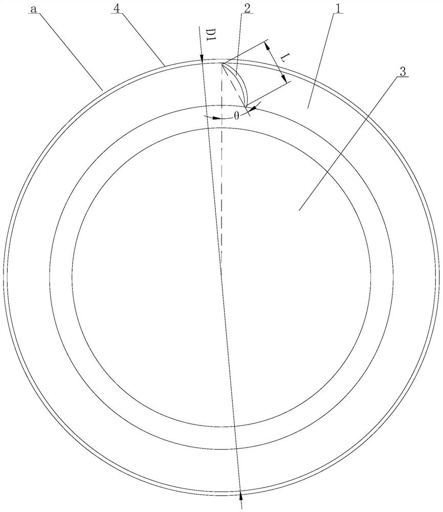
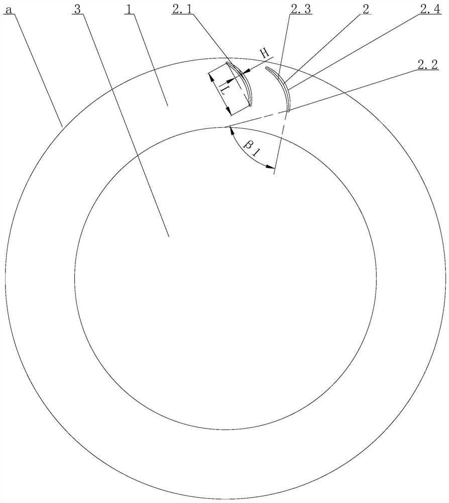
[0016] see Figure 1-Figure 2 , the high-efficiency cross-flow wind wheel includes at least one middle-section wind blade a, the middle-section wind blade a includes a middle plate 1, and a plurality of blades 2 are annularly arranged on the peripheral side of the middle plate 1. The blades 2 are short-chord blades, and the effective The outer diameter (i.e. the diameter of the tangential circle of the end arcs of all blades 2 close to the outside of the blade) is D1, the chord length of the blade 2 (i.e. the length of the common tangent line of the arcs at both ends of the blade 2) is L, 0.095


PUM


Abstract

An efficient cross-flow wind wheel comprises at least one middle-section wind wheel. The middle-section wind wheel comprises a middle plate, wherein a plurality of blades are annularly arranged on the peripheral side of the middle plate, the blades are short-chord blades, the effective outer diameter of each blade is D1, the chord length of each blade is L, L/D1 is larger than 0.095 and smaller than 0.115, the inclination angle theta of each blade is larger than or equal to 27 degrees and smaller than or equal to 30 degrees, the camber of the blade is H, the maximum relative camber of the blade is H/L, H/L is larger than or equal to 0.17 and smaller than or equal to 0.21, and the maximum relative camber position of the blade is distributed at the 1/4-1/2 position of the front edge of the blade. The short-chord-structure blade design is adopted, the weight of the wind wheel can be reduced on the premise that the performance of an air conditioner can be kept, and therefore the production cost of the wind wheel is saved, the short-chord-structure blade design is adopted, the distance between the blades and a hub is effectively increased, the airflow diffusion effect is improved, airflow flows into the inclination angles of the blades more advantageously, and the interaction between airflow and the blades is effectively reduced, so that the pressure pulsation is weakened, the efficiency of a fan is improved, and the aim of effectively reducing noise is fulfilled.

Description

technical field [0001] The invention relates to the technical field of fans, in particular to a high-efficiency cross-flow wind wheel. Background technique [0002] Such as image 3 As shown, the traditional cross-flow wind wheel generally adopts the blade 11 of the long chord structure, and the distance from the end of the blade 11 to the hub is relatively short, and a natural wind blowing method disclosed on October 27, 2020 is also shown in Chinese Patent Document No. CN211778195U. The cross-flow wind rotor includes an upper end cover, a lower end cover, an annular middle plate and blades, and the blades are distributed around between the upper end cover and the annular middle plate, or between the annular middle plate and the adjacent annular Between the middle plates, or between the ring-shaped middle plate and the lower end cover, the middle section wind blade layer is formed; the extension line of the blade is inclined relative to the rotation axis of the cross-flow w...

Claims


Application Information

Patent Timeline
IPC IPC(8): F04D29/30F04D29/66F24F13/24
CPCF04D29/30F04D29/666F24F13/24
Inventor 覃万翔王汉波韦宏茂叶涛
Owner GUANGDONG SUNWILL PRECISING PLASITC CO LTD
Why Eureka
Try Eureka