
Novel limiting mechanism

A limit structure, a new type of technology, applied in the direction of mechanical equipment, fixing devices, etc., can solve the problems of safety accidents, waste of time, and inability to ensure the firmness of objects, and achieve the effect of convenient operation and simple structure

Inactive Publication Date: 2014-12-03
YANTAI JEREH PETROLEUM EQUIP & TECH CO LTD
View PDF5 Cites 2 Cited by
  • Summary
  • Abstract
  • Description
  • Claims
  • Application Information

AI Technical Summary

Problems solved by technology

[0002] At present, some objects that can be easily and quickly disassembled need to be placed on oilfield operating vehicles or skid-mounted equipment. Usually, objects are bound by bolts or fastening straps, which are often complicated and troublesome when they need to be installed or unloaded. , a waste of time, it is not possible to ensure the firmness of the object, and it is easy to cause some safety accidents at work

Method used


Image

  • Novel limiting mechanism
  • Novel limiting mechanism
  • Novel limiting mechanism

Examples


Embodiment Construction

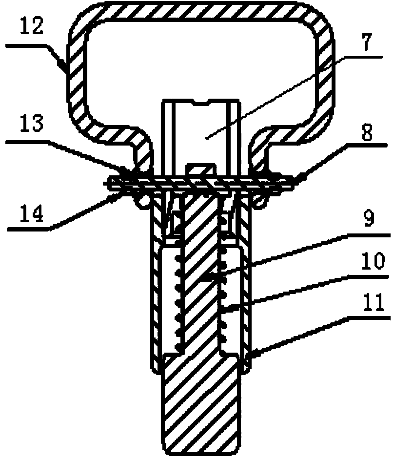
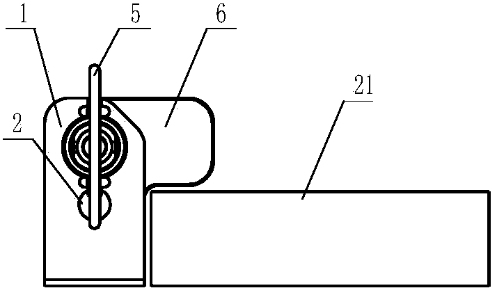
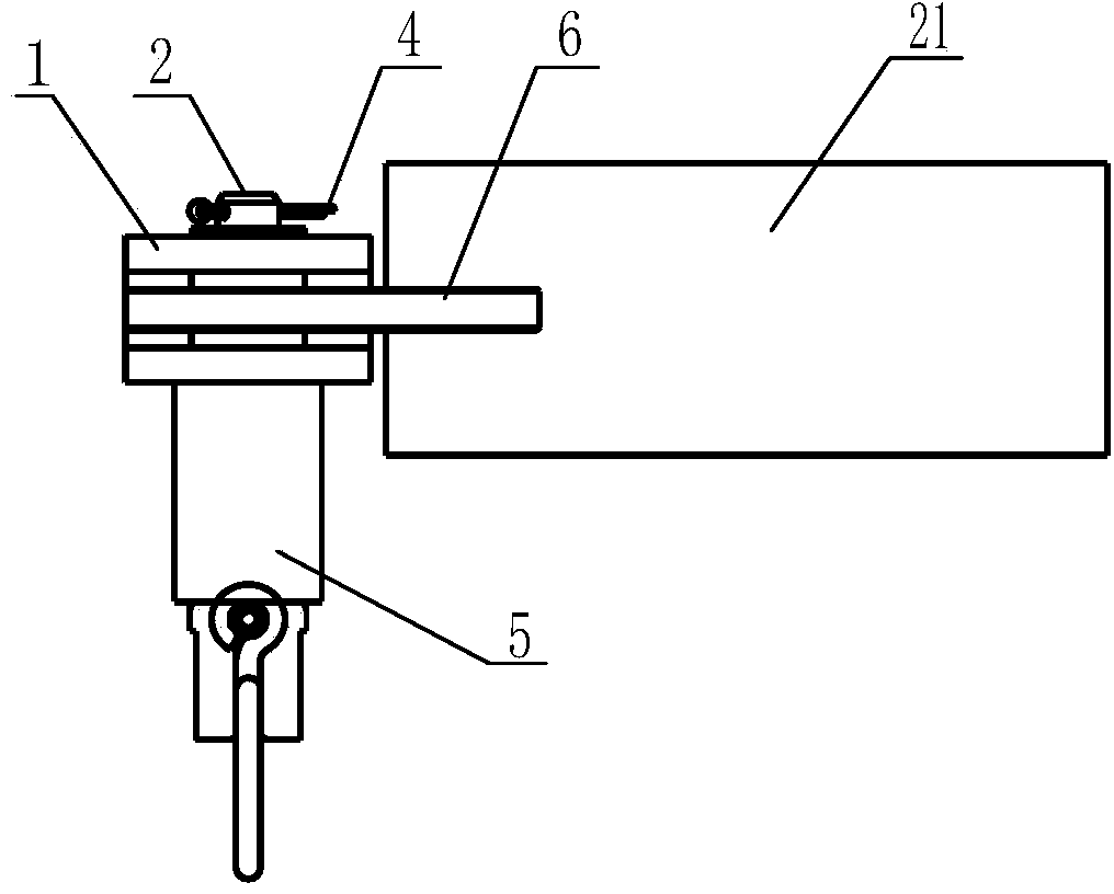
[0028] The principles and features of the present invention are described below in conjunction with the accompanying drawings, and the examples given are only used to explain the present invention, and are not intended to limit the scope of the present invention.

[0029] Such as Figure 1 to Figure 7 As shown, it is a structural schematic diagram of a new type of limiting structure, including a mounting seat 1, a spring pin 5, a limiting plate 6, and a pin shaft 2. The limiting plate 6 is preferably an L-shaped rocker mechanism. When rotating, When one end of the limiting plate 6 is pressed against the object 21, the other end is fixed with the inner spring pin 5 of the mounting seat 1; A limiting hole 15 is provided at the position of the limiting plate 6, and a second pin hole 20 corresponding to the shape of the limiting plate 6 is provided on the mounting base 1 . The limiting plate 6 is movably connected to the inside of the mounting seat 1 through the pin shaft 2, and ...


PUM


Abstract

The invention relates to a limiting mechanism, particularly to operating vehicle-mounted or skid-mounted equipment used for the field of oilfield equipment. The novel limiting mechanism comprises a mounting seat, a spring pin, a limiting plate and a pin shaft, wherein the limiting plate adopts a rocker arm mechanism; a round first pin shaft hole is formed in the limiting plate; the limiting plate penetrates the first pin shaft hole through the pin shaft, and is movably connected to the inside of the mounting seat; a round limiting hole is formed near the first pin shaft hole; one end of a spring pin penetrates through the limiting hole; the spring pin realizes limitation through the coordination with the limiting hole on the limiting plate. The core shaft is driven to move back and forth by pulling a handle, so that a double end stud can slide along the groove until the double end stud is rotated to be clamped to a limiting groove, the core shaft can be inserted into the limiting hole to achieve a fixing function, and the limiting can be relieved through a rotating manner. The device is simple in structure, convenient to operate and firm in fixing.

Description

technical field [0001] The invention relates to a position limiting mechanism, in particular to a vehicle-mounted or skid-mounted equipment used in the field of oil field equipment. Background technique [0002] At present, some objects that can be easily and quickly disassembled need to be placed on oilfield operating vehicles or skid-mounted equipment. Usually, objects are bound by bolts or fastening straps, which are often complicated and troublesome when they need to be installed or unloaded. , a waste of time, it is not possible to ensure the firmness of the object, and it is easy to cause some safety accidents at work. Therefore, a device with simple structure, convenient operation and firm fixing is needed. Contents of the invention [0003] The main purpose of the present invention is to overcome the above-mentioned shortcomings existing in the prior art, and provide a limiting device, which can drive the mandrel by rotating the limiting plate and pulling the hand...

Claims


Application Information

Patent Timeline
Patent Type & Authority Applications(China)
IPC IPC(8): F16B1/02
Inventor 彭述军魏晓光徐博车龙刚
Owner YANTAI JEREH PETROLEUM EQUIP & TECH CO LTD
Learn More