Axial vibration resistance type mechanical sealing device

A mechanical sealing device and axial vibration technology, which is applied in the direction of engine sealing, mechanical equipment, engine components, etc., can solve problems such as poor shock resistance, and achieve the effects of eliminating axial vibration, reducing axial vibration, and high stability

Active Publication Date: 2014-12-03
ZHEJIANG UNIV OF TECH
View PDF6 Cites 13 Cited by
  • Summary
  • Abstract
  • Description
  • Claims
  • Application Information

AI Technical Summary

Problems solved by technology

[0005] The present invention overcomes the disadvantage of poor axial vibration resistance in the prior art, and provides an anti-axial vibration mechanical seal device, which can eliminate the axial vibration generated by the unit shaft under axial excitation of a certain frequency

Method used


Image

  • Axial vibration resistance type mechanical sealing device
  • Axial vibration resistance type mechanical sealing device
  • Axial vibration resistance type mechanical sealing device

Examples


Embodiment 1

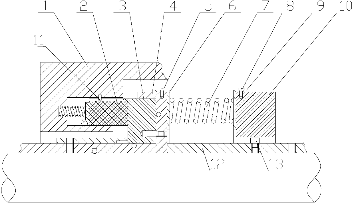
[0025] Refer to attached figure 1 :

[0026] figure 1 It is a structural schematic diagram of Embodiment 1 of the present invention. The axial vibration-resistant mechanical seal device includes a static ring seat 1, a static ring 2, a moving ring 3, a moving ring seat 4, a spring vibrator system and other related parts. The spring vibrator system includes a first spring seat 6, an elastic element 7. Screw 8, second spring seat 9, vibrator 10.

[0027] The axial vibration-resistant mechanical seal device includes a seal pair formed by the contact between the moving ring 3 and the static ring 2. The vertical direction of the sealing end faces of the moving ring 3 and the static ring 2 is defined as the axial direction. The moving ring 3 is set in the moving ring seat 4, the static ring 2 is set in the static ring seat 1, and the moving ring seat 4 and the static ring seat 1 are fixed on the base 12; The spring vibrator system composed of the vibrator 10, the elastic compone...

Embodiment 2

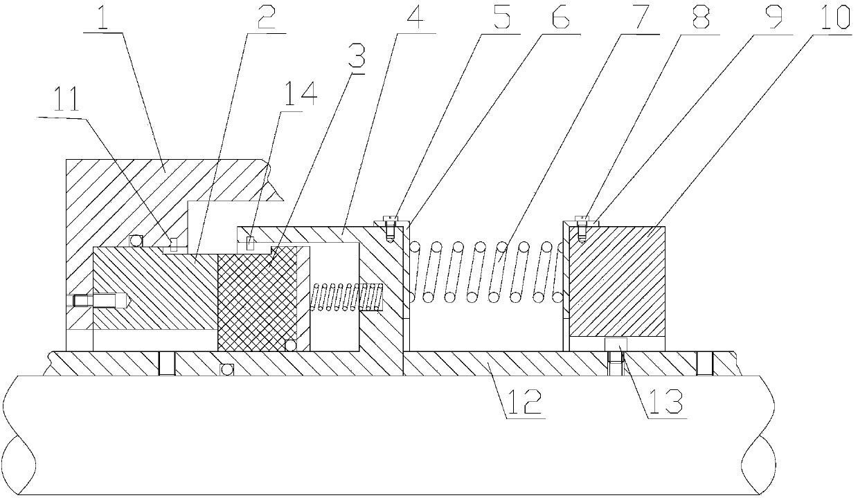
[0037] Refer to attached figure 2 :

[0038] figure 2 It is a structural schematic diagram of Embodiment 2 of the present invention. Its key technical requirements are basically the same as those of Embodiment 1, the main difference is that the static ring 2 in Embodiment 2 is fixedly installed on the static ring seat 1, and the moving ring 3 is flexibly installed on the moving ring seat 3, that is, the The above-mentioned moving ring 3 is flexibly connected to the moving ring seat 4, the moving ring 3 has only an axial degree of freedom, and the static ring 2 is fixed on the static ring seat 1.

[0039] The specific structure that restricts the moving ring 3 to only have the axial degree of freedom is: the moving ring 3 is provided with a third axial through groove, the moving ring seat 4 is provided with a third pin 14, and the third pin 14 is inserted into the In the third axial through groove.

Embodiment 3

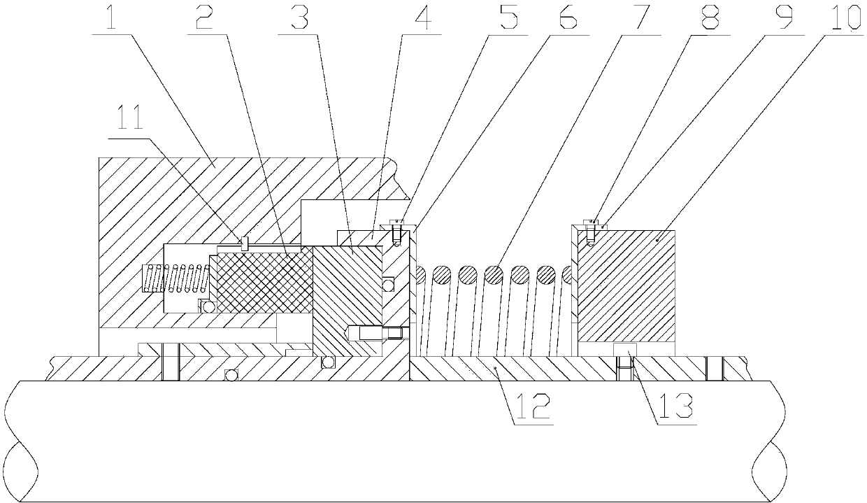
[0041] Refer to attached image 3 :

[0042] image 3 It is a structural schematic diagram of Embodiment 3 of the present invention. Its sealing structure and key technical requirements are basically the same as those in Embodiment 1. The main difference is that the elastic element 7 in the spring vibrator system in Embodiment 3 is a large spring. The total stiffness of the small cloth spring.


PUM


Abstract

An axial vibration resistance type mechanism sealing device comprises a sealing pair formed by contacting a moving ring with a static ring, wherein the perpendicular direction of the sealing end surface of the moving ring and the static ring is defined as the axial direction. The axial vibration resistance type mechanism sealing device is characterized in that the moving ring is arranged in a moving ring seat, the static ring is arranged in a static ring seat, and the moving ring seat and the static ring seat are fixedly connected onto a base; the mechanical sealing device further comprises a spring vibrator system consisting of an elastic assembly and a vibrator, the elastic assembly is connected with the moving ring seat and the vibrator, and the vibrator only has the axial freedom degree; and the static ring and the static ring seat are in flexible connection, the static ring only has the axial freedom degree, the moving ring is fixedly connected onto the moving ring seat, or, the moving ring and the moving ring seat are in flexible connection, the moving ring only has the axial freedom degree, and the static ring is fixedly connected onto the static ring seat.

Description

technical field [0001] The invention relates to a shaft end seal of a rotating machine, in particular to a shaft end seal of a rotating machine with a certain axial vibration frequency or axial vibration within a certain frequency range. Background technique [0002] Mechanical seals are widely used in shaft end seals of rotating machinery due to their significant performance advantages such as low leakage, low power consumption, and long life, such as compressors, pumps, reactors, fans and other rotating machinery. However, in many rotating machines, due to the complexity of the working conditions, the shaft has severe axial vibration, which destroys the stable operation of the mechanical seal and limits the further promotion of the mechanical seal. The specific manifestations are: the seal end face of the contact mechanical seal is severely worn under the condition of severe axial vibration, and the seal life and performance decline rapidly; while for the non-contact mecha...

Claims


Application Information

Patent Timeline
Patent Type & Authority Applications(China)
IPC IPC(8): F16J15/16F16F7/104
Inventor 彭旭东陈源白少先孟祥铠杨笑李纪云
Owner ZHEJIANG UNIV OF TECH
Why Eureka
Try Eureka