Microwave oven refrigerator draught fan control method and device and microwave oven refrigerator

A control method and technology of microwave ovens, which are applied to household refrigeration devices, lighting and heating equipment, household appliances, etc., can solve the problems of inability to install anti-condensation pipes, affect user comfort, affect refrigerator power consumption, etc., and meet the needs of convenience. Sexual demands, shortening unnecessary working hours, and reducing power consumption

Active Publication Date: 2014-12-03
GUANGZHOU MIDEA HUALING REFRIGERATOR
View PDF4 Cites 8 Cited by
  • Summary
  • Abstract
  • Description
  • Claims
  • Application Information

AI Technical Summary

Problems solved by technology

[0002] The microwave oven refrigerator is the first in the industry. Because it breaks the conventional refrigerator pattern and embeds the microwave oven in the refrigerator, the integrity of the refrigerator is broken due to the addition of the microwave oven, and the refrigerator is a refrigeration component. The lower part of the microwave oven is connected to the freezer, so it cannot be installed around it Therefore, the lower surface of the microwave oven is prone to condensation. In order to solve this problem, the continuous operation of the fan is often used to avoid condensation, but this working method greatly affects the consumption of the refrigerator. The power, and the noise generated when the wind is working will also affect the comfort of the user during use, and continuous work is also a relatively large test for the reliability of the fan

Method used


Image

  • Microwave oven refrigerator draught fan control method and device and microwave oven refrigerator
  • Microwave oven refrigerator draught fan control method and device and microwave oven refrigerator
  • Microwave oven refrigerator draught fan control method and device and microwave oven refrigerator

Examples


Embodiment Construction

[0037] In order to understand the above-mentioned purpose, features and advantages of the present invention more clearly, the present invention will be further described in detail below in conjunction with the accompanying drawings and specific embodiments. It should be noted that, in the case of no conflict, the embodiments of the present application and the features in the embodiments can be combined with each other.

[0038] In the following description, many specific details are set forth in order to fully understand the present invention. However, the present invention can also be implemented in other ways than described here. Therefore, the protection scope of the present invention is not limited by the specific implementation disclosed below. Example limitations.

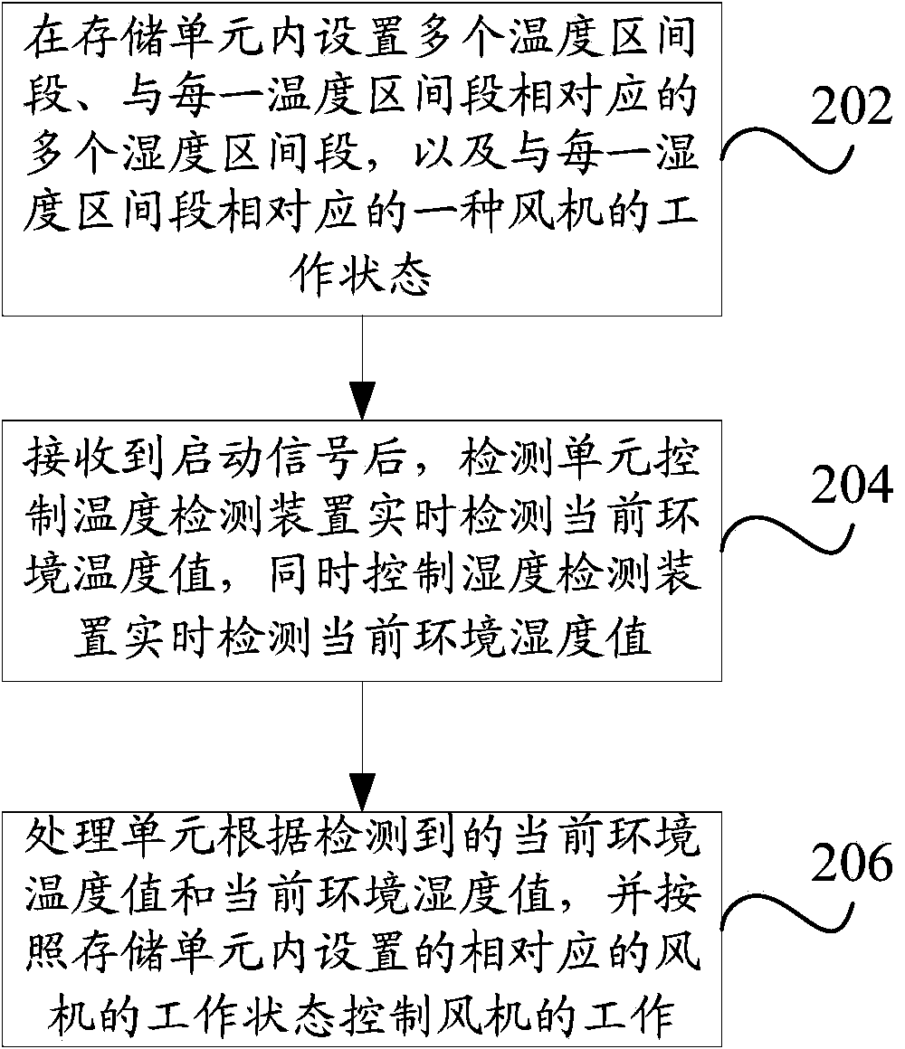
[0039] figure 1 A schematic flowchart of a control method for an air conditioner according to an embodiment of the present invention is shown.

[0040] Such as figure 1 As shown, some embodiments of the pr...


PUM


Abstract

The invention provides a microwave oven refrigerator draught fan control method and device and a microwave oven refrigerator. The microwave oven refrigerator draught fan control method includes the steps of setting a plurality of temperature ranges in a storage unit, a plurality of humidity ranges respectively corresponding to the temperature ranges and draught fan working states respectively corresponding to the humidity ranges; simultaneously controlling a temperature detectiondevice and a humidity detection device for detecting values of the current ambient temperature and the current ambient humidity in real time through a detection unit after receiving a start signal; controlling the draught fan to work through a processing unit according to the detected values of the current ambient temperature and the current ambient humidity and corresponding draught fan working states set in the storage unit. According to the technical scheme of the microwave oven refrigerator draught fan control method and device and the microwave oven refrigerator, condensation on the lower surface of a microwave oven box can be prevented and unnecessary draught fan working hours can be reduced or avoided, so that the working efficiency and use performance of a draught fan can be improved and further the power consumption of the microwave oven refrigerator can be reduced.

Description

technical field [0001] The present invention relates to the technical field of microwave ovens and refrigerators, and more specifically, to a control method for microwave ovens and refrigerators, a control device for fans of microwave ovens and refrigerators, and a microwave oven refrigerator including the control device. Background technique [0002] The microwave oven refrigerator is the first in the industry. Because it breaks the conventional refrigerator pattern and embeds the microwave oven in the refrigerator, the integrity of the refrigerator is broken due to the addition of the microwave oven, and the refrigerator is a refrigeration component. Therefore, the lower surface of the microwave oven is prone to condensation. To solve this problem, the continuous operation of the fan is often used to avoid condensation, but this working method greatly affects the consumption of the refrigerator. The power, and the noise generated when the wind is working will also affect t...

Claims


Application Information

Patent Timeline
Patent Type & Authority Applications(China)
IPC IPC(8): F25D29/00F25D23/12
Inventor 张闪马瑞
Owner GUANGZHOU MIDEA HUALING REFRIGERATOR
Why Eureka
Try Eureka