
A test unit for array substrate, array substrate and display device

A technology for testing units and array substrates, applied in electrical components, optics, instruments, etc., can solve the problems of increasing the preparation cost of array substrates, misjudging test results, consuming a lot of manpower and material resources, etc., and reducing the possibility of poor contact Sexuality, increasing the size of the area, and improving the effect of accuracy

Active Publication Date: 2017-04-19
TCL CHINA STAR OPTOELECTRONICS TECH CO LTD
View PDF4 Cites 0 Cited by
  • Summary
  • Abstract
  • Description
  • Claims
  • Application Information

AI Technical Summary

Problems solved by technology

[0004] The inventors found that in the prior art, the position of the test structure is lower than the position of the metal substrate, therefore, the contact between the test structure and the metal substrate needs to be realized by climbing the test structure
However, the climbing part of the test structure is prone to breakage and other poor contact phenomena, which will cause misjudgment of the test results and require a lot of manpower and material resources to clean up, which not only increases the preparation cost of the array substrate but also reduces the preparation efficiency.

Method used


Image

  • A test unit for array substrate, array substrate and display device
  • A test unit for array substrate, array substrate and display device

Examples


Embodiment Construction

[0023] The implementation of the present invention will be described in detail below in conjunction with the accompanying drawings and examples, so as to fully understand and implement the process of how to apply technical means to solve technical problems and achieve technical effects in the present invention. It should be noted that, as long as there is no conflict, each embodiment and each feature in each embodiment of the present invention can be combined with each other, and the formed technical solutions are all within the protection scope of the present invention.

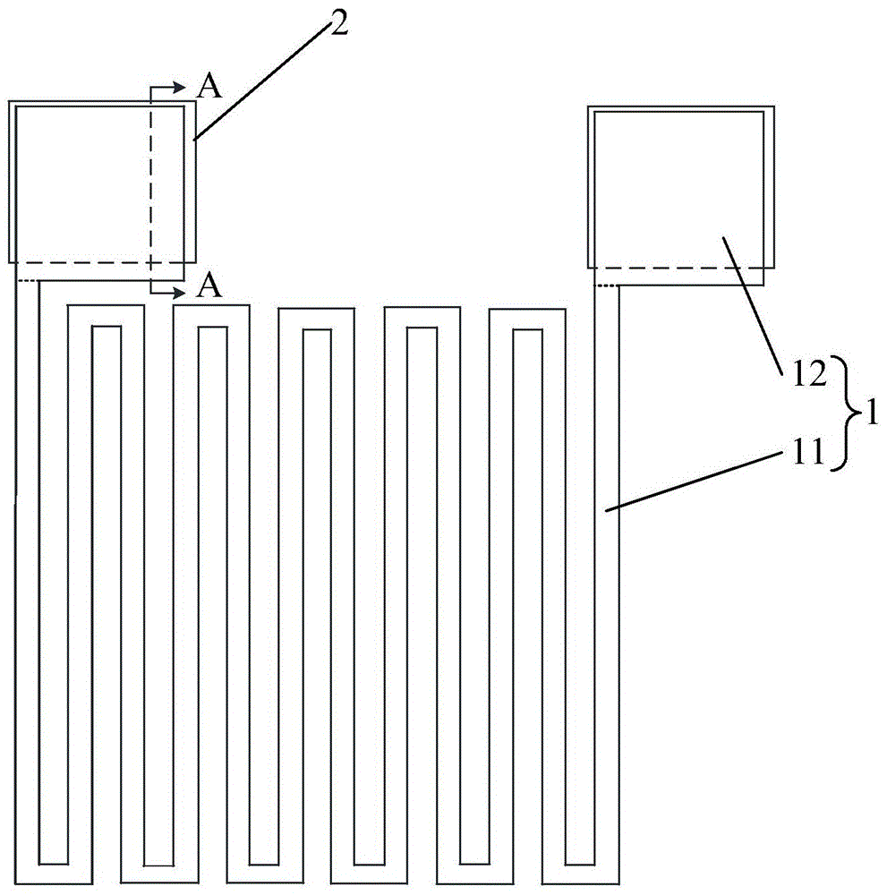
[0024] The first aspect of this embodiment provides a test unit for an array substrate, such as figure 1 As shown, the test unit includes a test structure 1 and two metal substrates 2, wherein the test structure 1 includes a connection portion 11 and two contact portions 12, wherein the contact portion 12 is located between the corresponding metal substrates 2 and in contact with the metal substrate 2 , the ...


PUM


Abstract

A test unit for an array substrate, an array substrate and a display apparatus, which belong to the technical field of displays, can prevent the occurrence of bad phenomena that a climbing position of a test structure (1) is broken and the like, and ensure the accuracy of a test result. The test unit for an array substrate comprises the test structure (1) and two metal substrates (2), wherein the test structure (1) comprises a connecting part (11) and two contact parts (12), each contact part (12) is located above the corresponding metal substrate (2) and is in contact with the metal substrate (2), the connecting part (11) is connected to the two contact parts (12), and a connecting position of any one of the contact parts (12) and the connecting part (11) is located outside a corresponding region of the corresponding metal substrate (2).

Description

technical field [0001] The present invention relates to the field of display technology, in particular to a test unit for an array substrate, an array substrate and a display device. Background technique [0002] A liquid crystal display (LCD for short) is a mainstream display device at present. A liquid crystal display is mainly composed of an array substrate, a color filter substrate, peripheral circuits, and a backlight assembly. Among them, the array substrate is a glass substrate with specific specifications, and a certain number of pixels are formed on the glass substrate through a series of processes such as coating, exposure, and etching. Each pixel includes three sub-pixels of different colors. A pixel is the smallest display component of an array substrate. The normal operation of each sub-pixel ensures that the liquid crystal display can display pictures normally. [0003] The production process of the liquid crystal display, especially the production process o...

Claims


Application Information

Patent Timeline
Patent Type & Authority Patents(China)
IPC IPC(8): G02F1/13
CPCG02F1/1343H01L23/50H01L2924/0002H01L2924/00
Inventor 徐向阳
Owner TCL CHINA STAR OPTOELECTRONICS TECH CO LTD
Learn More