Touch panel

A technology of touch panel and contact opening, which is applied in the direction of instruments, electrical digital data processing, electrical components, etc., and can solve problems such as unfavorable narrow borders and affecting product competitiveness

Inactive Publication Date: 2014-12-03
WINTEK CORP
View PDF5 Cites 15 Cited by
  • Summary
  • Abstract
  • Description
  • Claims
  • Application Information

AI Technical Summary

Problems solved by technology

However, under the above-mentioned traditional touch panel structure, it is not conducive to achieve the effect of narrow borders, which in turn affects the competitiveness of products

Method used


Image

  • Touch panel
  • Touch panel
  • Touch panel

Examples


Embodiment Construction

[0084]In order to enable those skilled in the technical field of the present invention to further understand the present invention, several preferred embodiments of the present invention are enumerated below, together with the accompanying drawings, to describe the composition of the present invention in detail.

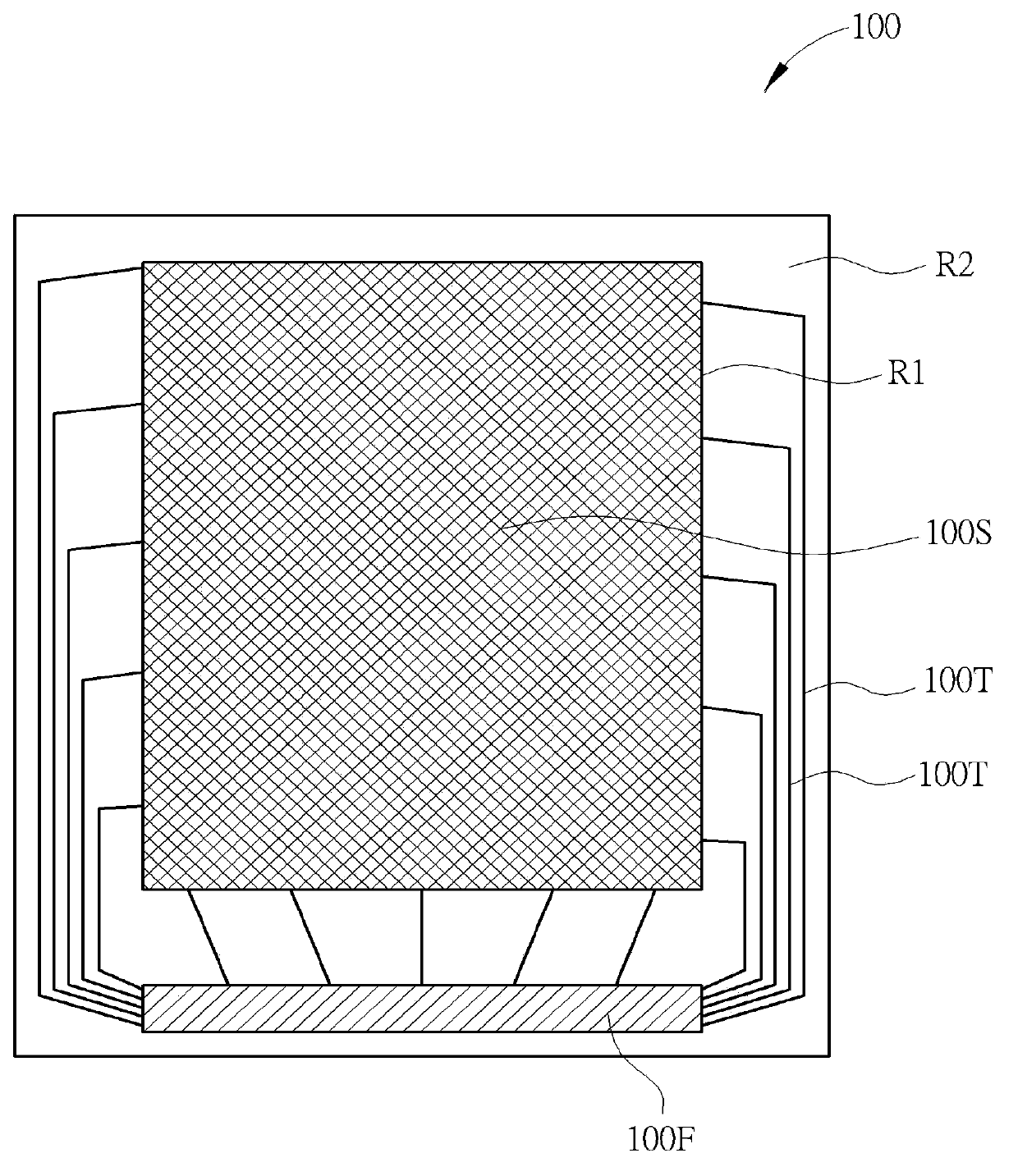
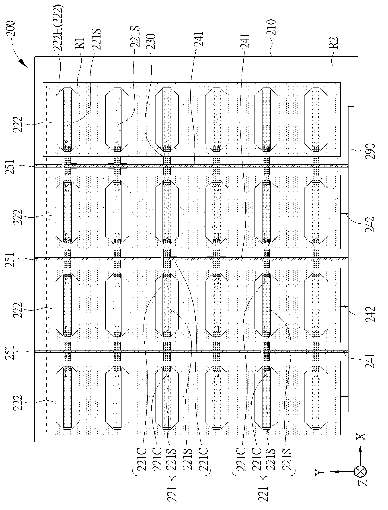
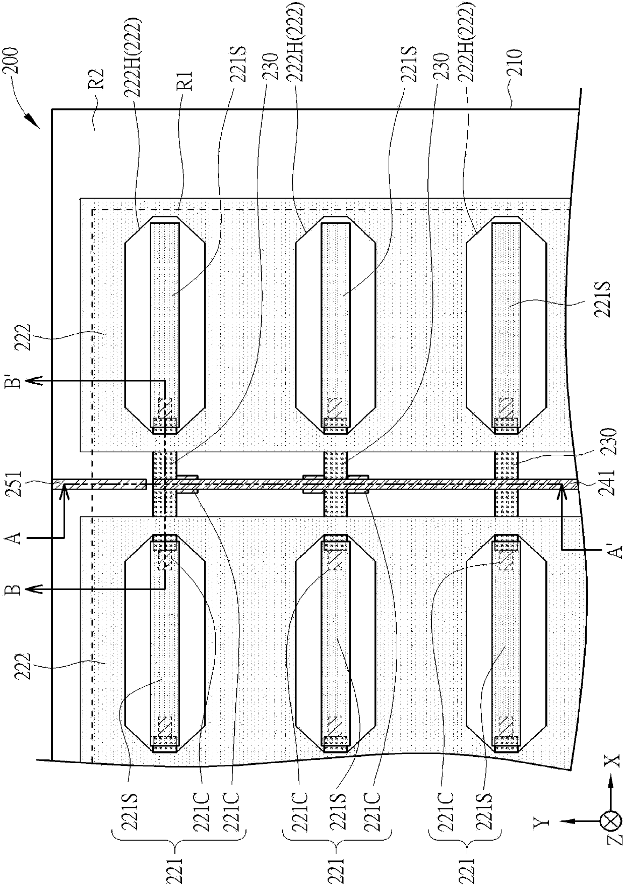
[0085] Please refer to Figure 2 to Figure 5 . figure 2 Shown is a schematic diagram of a touch panel according to a first preferred embodiment of the present invention. image 3 for figure 2 A partially enlarged schematic diagram. Figure 4 for along image 3 The cross-sectional view shown by the line A-A' in the middle. Figure 5 for along image 3 The cross-sectional view drawn by the line B-B' in the middle. For the convenience of description, the drawings of the present invention are only schematic diagrams for easy understanding of the present invention, and the detailed proportions thereof can be adjusted according to design requirements. like Figur...


PUM


Abstract

A touch panel, having a viewing region and a peripheral region adjacent to at least one edge of the viewing region, includes a plurality of first axis electrodes, a plurality of second axis electrodes, and a plurality of first traces. The first axis electrodes are disposed in the viewing region and extend along a first direction. The second axis electrodes are disposed in the viewing region and extend along a second direction. The first direction is not parallel to the second direction. The first traces are at least partially disposed in the viewing region. Each of the first traces is electrically connected to at least one of the first axis electrodes. The first traces extend from the viewing region to the peripheral region.

Description

technical field [0001] The invention relates to a touch panel, in particular to a touch panel in which wiring is arranged in an opening area to reduce the size of the surrounding area. Background technique [0002] The technology development of the touch panel is very diverse, and the more common technologies currently include resistive, capacitive, and optical. Among them, the capacitive touch panel has become the mainstream touch technology used in mid-to-high-end consumer electronic products due to its characteristics of high accuracy, multi-touch, high durability, and high touch resolution. The operating principle of the capacitive touch panel is to use the sensing electrodes to detect the capacitance change of the touch points, and use the connecting wires connecting the electrodes on different axes to transmit the signals back to complete the positioning. [0003] Please refer to figure 1 . figure 1 Shown is a schematic diagram of a conventional touchpad. like fig...

Claims


Application Information

Patent Timeline
Patent Type & Authority Applications(China)
IPC IPC(8): G06F3/041G06F3/044
CPCH03K17/9622G06F3/0443G06F3/0446G06F3/0448
Inventor 李卓谕詹绣璘叶政谚陈昱廷苏国彰
Owner WINTEK CORP
Why Eureka
Try Eureka