Transformer rebreather structure

A transformer and respirator technology, applied in the field of transformer respirator structure, can solve problems affecting product use, oil leakage, etc., and achieve the effect of ensuring normal operation and eliminating the oil cup structure

Active Publication Date: 2014-12-03
STATE GRID CORP OF CHINA +2
View PDF5 Cites 12 Cited by
  • Summary
  • Abstract
  • Description
  • Claims
  • Application Information

AI Technical Summary

Problems solved by technology

However, the structure of the existing respirator all adopts the above-mentioned oil cup structure, but the oil stored in the oil cup will leak during installation and transportation, thus affecting the subsequent use of the product

Method used


Image

  • Transformer rebreather structure

Examples


Embodiment Construction

[0011] In order to make the above-mentioned features and advantages of the present invention more comprehensible, the following specific embodiments are described in detail with reference to the accompanying drawings.

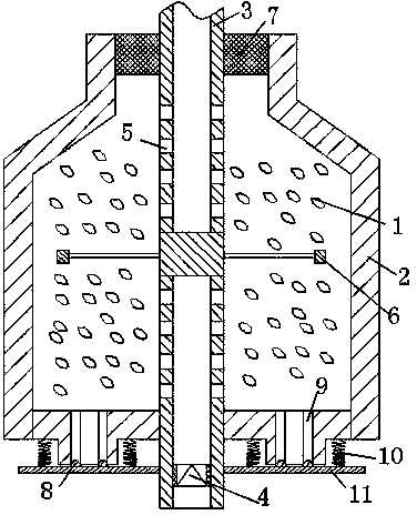
[0012] refer to figure 1 , the present invention relates to a transformer respirator structure, including a breathing tank 1 equipped with a desiccant 2, a breathing tube 3 connected to the internal oil circuit of the transformer is installed in the breathing tank 1, and the breathing tube runs through Breathing tank, described breathing tube comprises the air-guiding section that is positioned at breathing tank and is positioned at the free section outside breathing tank, is provided with a one-way air valve 4 in the breathing tube that is positioned at free section, and the breathing tube that is positioned at air-guiding section includes being positioned at breathing tank The upper air guide tube on the upper side and the lower air guide tube located on the ...


PUM


Abstract

The invention relates to a transformer rebreather structure which comprises a breather tank filled with drying agents. A breather tube connected with an oil line in a transformer via a pipeline is arranged in the breather tank and penetrates through the breather tank. The transformer rebreather structure is characterized in that the breather tube comprises an air guide section located in the breather tank and a free section located outside the breather tank, a one-way air valve is arranged in the free section of the breather tube, the air guide section of the breather tube comprises an upper air guide tube located on the upper side of the breather tank and a lower air guide tube located on the lower side of the breather tank, the upper air guide tube and the lower air guide tube are in sealed connection, a plurality of air guide holes are formed in the walls of the upper air guide tube and the lower air guide tube, a vent hole is formed in the bottom of the breather tank, and a rubber sealing cover is connected with the bottom of the breather tank via a reset spring. By means of the transformer rebreather structure, an oil cup structure is omitted, product operating performance is not affected during equipment transportation and installation, and normal operation is guaranteed.

Description

technical field [0001] The invention relates to a transformer respirator structure, which meets the needs of the working process of the transformer. Background technique [0002] Transformer respirator is also called transformer hygroscopic device, or transformer silica gel tank, transformer desiccant, its function is to absorb the moisture in the air that enters the oil pillow plastic bag and diaphragm, and removes and dries the moisture that enters the transformer (or mutual inductance) due to the change of transformer oil temperature. The sundries and moisture in the air of the oil conservator) to prevent the transformer from being damp and to ensure the insulation strength of the transformer oil. When the transformer is heated and expands, the excess air inside the transformer is exhaled; when the transformer oil temperature decreases and contracts, the outside air is sucked in. When the outside air is sucked in, the transformer oil in the oil storage box filters the o...

Claims


Application Information

Patent Timeline
Patent Type & Authority Applications(China)
IPC IPC(8): H01F27/14
Inventor 陈大凤罗松林耀晖
Owner STATE GRID CORP OF CHINA
Why Eureka
Try Eureka