Permanent magnet for motor and design method thereof

A design method and technology of permanent magnets, applied in the direction of magnetic circuit rotating parts, magnetic circuit shape/style/structure, etc., can solve the problem that the average torque of the motor cannot be well controlled, reduce the torque density of the motor, the operating efficiency, Reduce problems such as the average torque of the motor, and achieve the effects of smooth operation, increased torque output, and high power density

Active Publication Date: 2014-12-03
NINGBO HAIBO GRP CO LTD
View PDF13 Cites 10 Cited by
  • Summary
  • Abstract
  • Description
  • Claims
  • Application Information

AI Technical Summary

Problems solved by technology

The shape of the permanent magnet in this patent reduces the torque ripple and tooth moment of the motor, but it cannot control the average torque of the motor very well, which is the same as the current method of using sinusoidal function processing to realize permanent magnets, such as figure 2 As shown, although this method can reduce the cogging torque and operating torque ripple of the motor, it also reduces the average torque of the motor at the same time, thereby reducing the torque density and operating efficiency of the motor

Method used


Image

  • Permanent magnet for motor and design method thereof
  • Permanent magnet for motor and design method thereof
  • Permanent magnet for motor and design method thereof

Examples


Embodiment Construction

[0033] The present invention will be further described in detail below in conjunction with the accompanying drawings.

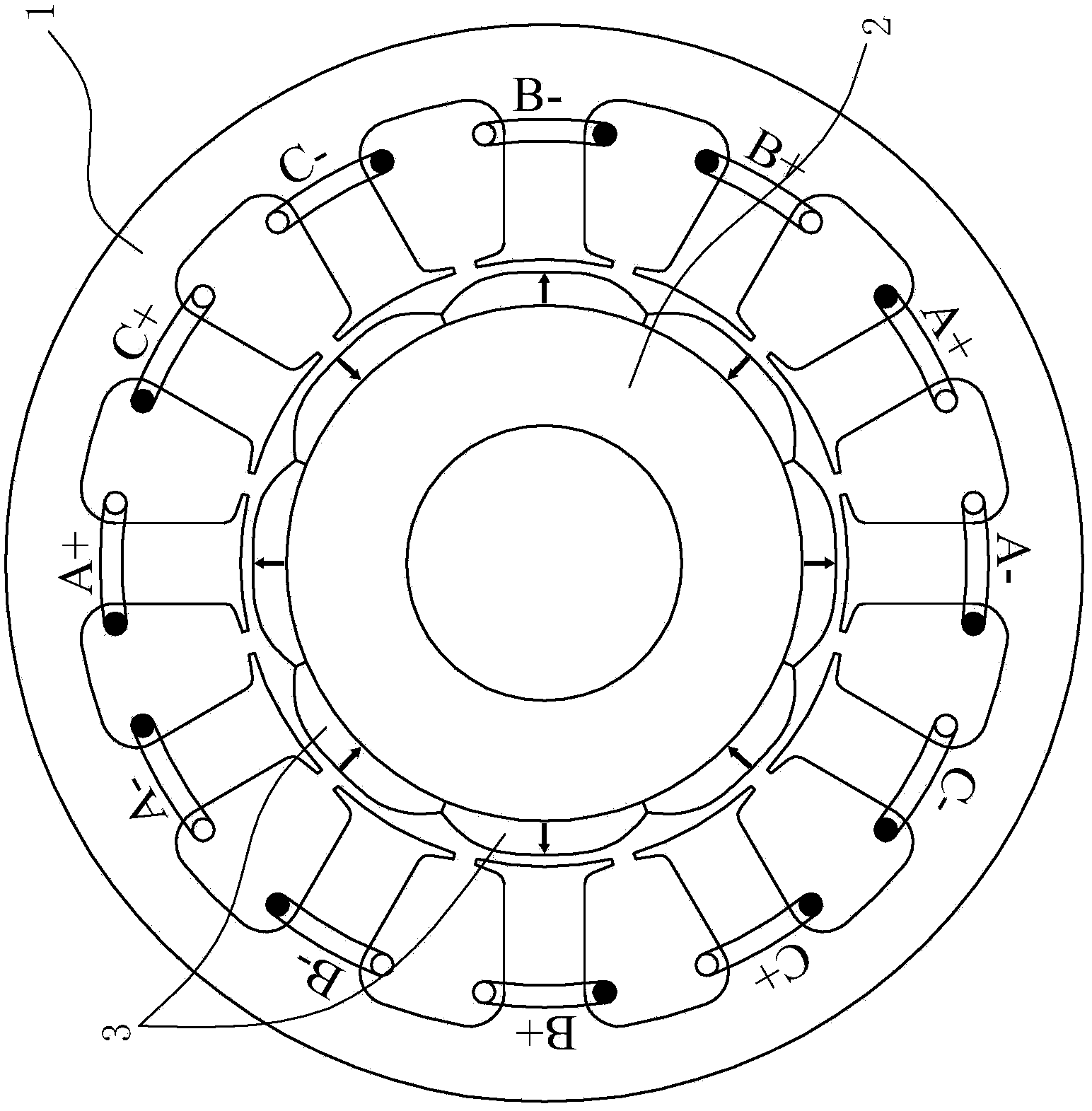
[0034] Such as Figure 3 ~ Figure 7 As shown, the present embodiment relates to a permanent magnet and a design method of the permanent magnet, and the permanent magnet of the present embodiment is used for a surface-mounted motor, such as image 3 Shown is the general assembly drawing of the motor. The motor is composed of a motor stator 1 and a motor rotor 2. The permanent magnet 3 is fixed on the surface of the motor rotor 2 by high-strength glue.

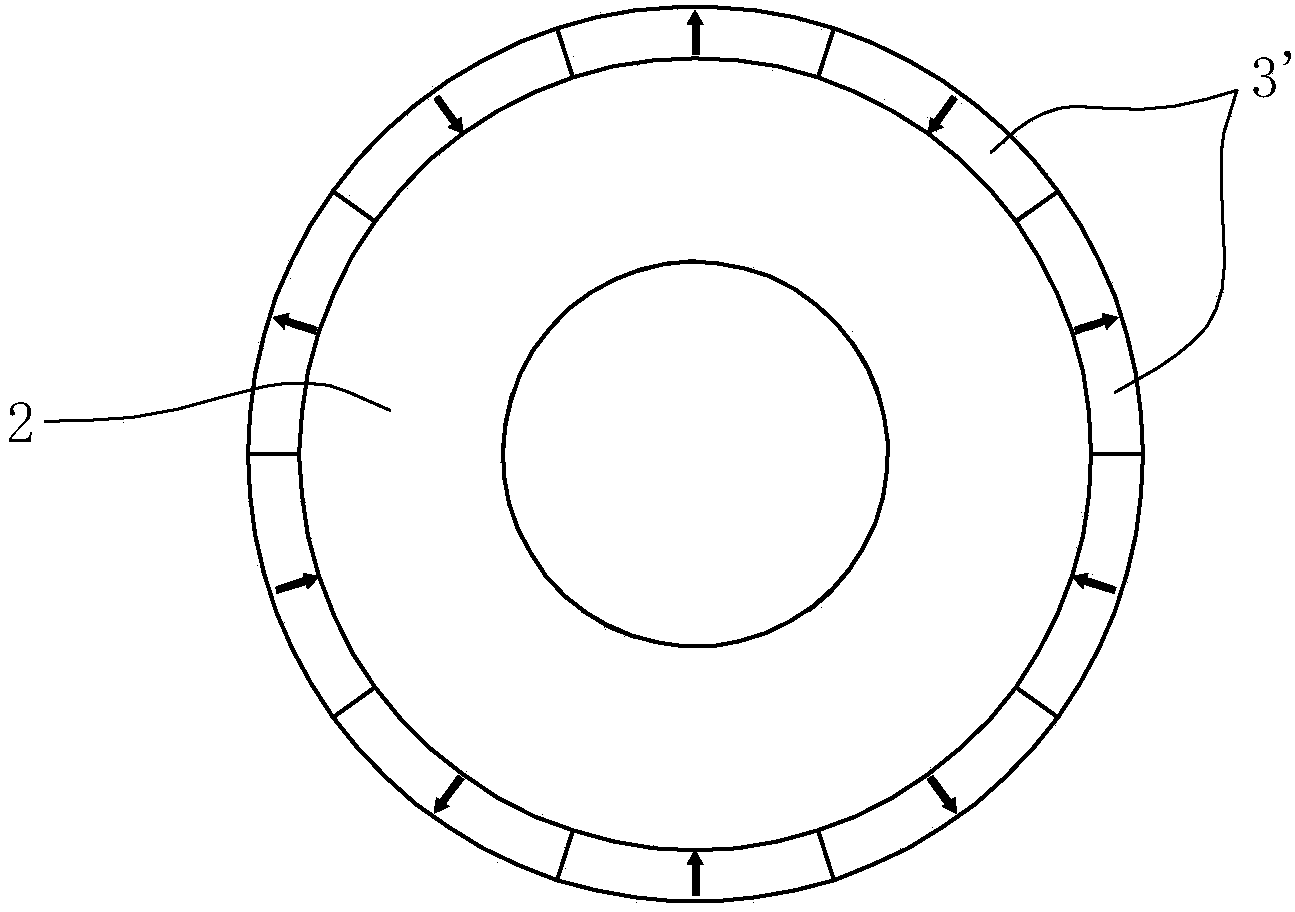
[0035] The distribution of the air gap magnetic field when the motor is working is closely related to the shape of the permanent magnet. The traditional permanent magnet 3' is usually as follows figure 1 As shown in the rectangular structure, the square wave distribution generated by the permanent magnet 3' has high harmonic content in the magnetic field, which leads to large fluctuations in the cogging torque...


PUM


Abstract

The invention relates to a permanent magnet for a motor comprising a motor rotor and a motor stator, wherein an air gap is reserved between the motor rotor and the motor stator. The permanent magnet is characterized by comprising a base bottom surface and an upper top surface, wherein the base bottom surface is attached to the outer surface of the motor rotor, the upper top surface is arranged opposite to the air gap, the contour line of the upper top surface is a curve formed by superposing a sine wave and a triple frequency harmonic function, and the specific shape of the curve is determined by the function expressed by a formula as specified in the specification. The permanent magnet for the motor has the advantages that a new permanent magnet structure is obtained by adding the sine wave to the optimal triple frequency harmonic function, torque output is increased on the premise that torque pulsation of the motor is not increased, and the motor has the advantages of being high in power density and efficiency, smooth in operation, low in noise, capable of saving energy and the like.

Description

technical field [0001] The invention relates to a permanent magnet, in particular to a permanent magnet for a surface-mounted permanent magnet motor and a design method for the permanent magnet. Background technique [0002] The rotors of existing surface-mounted permanent magnet motors usually use permanent magnets that have not undergone pole-cutting treatment, such as figure 1 As shown, the outer section of the permanent magnet of this motor is cylindrical, and the air-gap magnetic field generated by the permanent magnet has a high harmonic content, which leads to a large cogging torque of the motor and a large pulsation of the operating torque, resulting in greater vibration and noise, affecting the control accuracy and positioning accuracy of the whole machine. [0003] In order to reduce the cogging torque and operating torque ripple of the motor, and improve the control accuracy of the equipment, in the prior art, there is an existing Chinese invention patent "Perman...

Claims


Application Information

Patent Timeline
Patent Type & Authority Applications(China)
IPC IPC(8): H02K1/27
Inventor 王凯贺定芳姚辉明石林武海云
Owner NINGBO HAIBO GRP CO LTD
Why Eureka
Try Eureka