
Photovoltaic power supply system and control method thereof

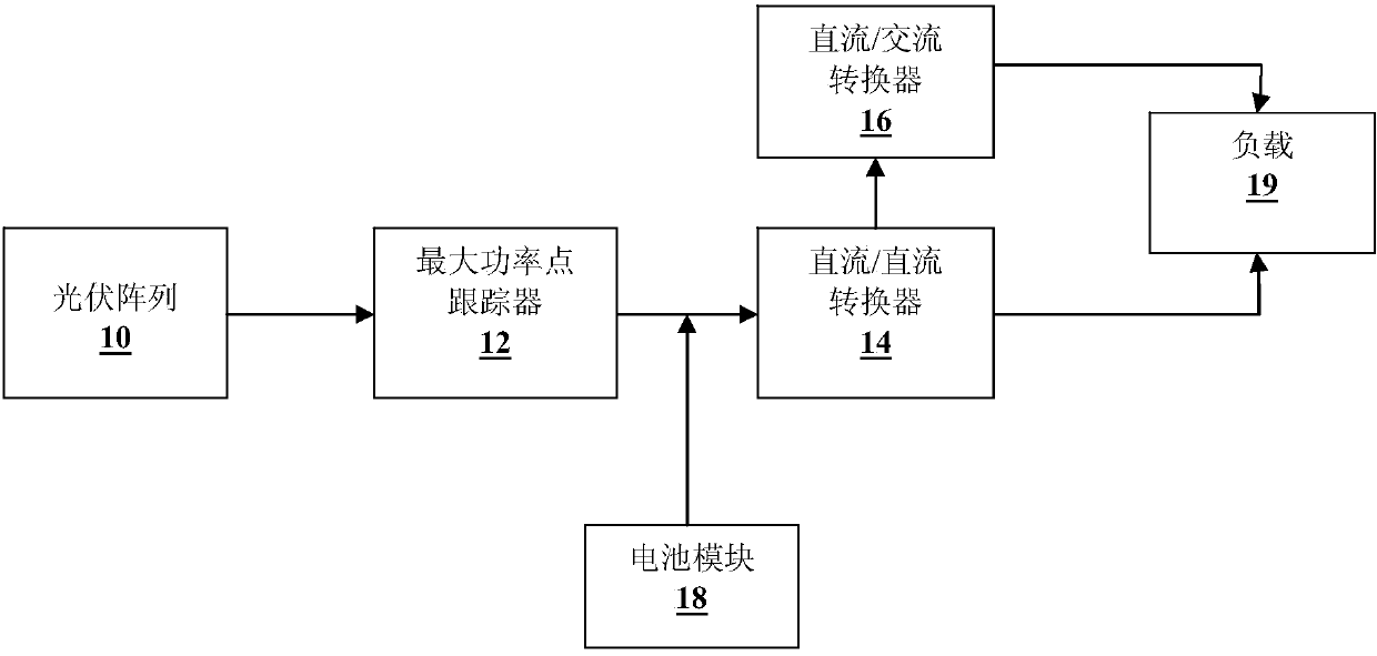
A power supply system, photovoltaic technology, applied in the direction of photovoltaic power generation, photovoltaic power stations, photovoltaic modules, etc., can solve the problems of unfavorable new energy application promotion, low photoelectric conversion efficiency, and many conversion links, so as to reduce devices, reduce energy loss, improve efficiency effect

Inactive Publication Date: 2014-12-03
SHANGHAI DIANJI UNIV
View PDF3 Cites 9 Cited by
  • Summary
  • Abstract
  • Description
  • Claims
  • Application Information

AI Technical Summary

Problems solved by technology

However, the above-mentioned photovoltaic power supply system has many conversion links, and each link will cause a non-negligible energy loss, thus reducing the photoelectric conversion efficiency of the entire photovoltaic power supply system. In addition, the cost of the aforementioned photovoltaic power supply system is relatively high. Not conducive to the promotion of new energy applications

Method used


Image

  • Photovoltaic power supply system and control method thereof
  • Photovoltaic power supply system and control method thereof
  • Photovoltaic power supply system and control method thereof

Examples


Embodiment Construction

[0021] A detailed description will be given below of embodiments of the present invention. Although the present invention will be described and illustrated in conjunction with some specific embodiments, it should be noted that the present invention is not limited to these embodiments. On the contrary, any modification or equivalent replacement made to the present invention shall be included in the scope of the claims of the present invention.

[0022] In addition, in order to better illustrate the present invention, numerous specific details are given in the specific embodiments below. It will be understood by those skilled in the art that the present invention may be practiced without these specific details. In other instances, well-known methods, processes, components and circuits are not described in detail so as to highlight the gist of the present invention.

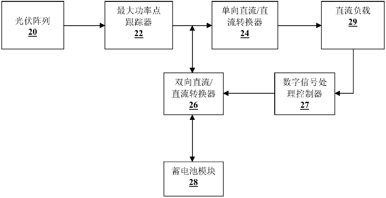
[0023] figure 2 Shown is a structural block diagram of a photovoltaic power supply system based on a bidirect...


PUM


Abstract

The invention discloses a photovoltaic power supply system and a control method thereof. The system and the method are used for supplying power to a direct-current load. The photovoltaic power supply system comprises a photovoltaic array used for converting light energy into electricity, a maximum power point tracker used for tracking the maximum power point in the photovoltaic array and outputting direct-current electricity, and a one-way DC / DC converter used for converting the direct-current electricity output by the maximum power point tracker into direct-current electricity of a preset level. The photovoltaic power supply system further comprises a two-way DC / DC converter. When electric power output by the photovoltaic array is larger than that needed by the direct-current load, the two-way DC / DC converter controls surplus electric power to be used for charging a storage battery module. When the electric power output by the photovoltaic array is less than that needed by the direct-current load, the two-way DC / DC converter controls the storage battery module to compensate lacking electric power needed by the direct-current load.

Description

technical field [0001] The invention relates to a light energy power supply system, in particular to a photovoltaic power supply system based on a bidirectional DC / DC converter and a control method thereof. Background technique [0002] figure 1 Shown is a structural block diagram of a photovoltaic power supply system in the prior art. As shown in the figure, the photovoltaic power supply system is used to supply power to loads 19 (for example, including DC loads and AC loads such as radiant furnaces, induction cookers, and refrigerators), which further include photovoltaic arrays 10 (for example, solar panels), and the maximum power A point tracker 12 (Maximum Power Point Tracking, MPPT for short), a DC / DC converter 14 , a DC / AC converter 16 and a battery module 18 . [0003] The working process of the photovoltaic power supply system is as follows: the electricity output by the photovoltaic array 10 passes through the MPPT12 to collect the maximum power point output by t...

Claims


Application Information

Patent Timeline
Patent Type & Authority Applications(China)
IPC IPC(8): H02S10/20H02M3/335G05F1/67
CPCY02E10/56Y02E70/30
Inventor 林贞汛蒋赢潘婷蓝培芝董玉龙唐良美黄远康贺翔宇
Owner SHANGHAI DIANJI UNIV
Learn More