Eureka AIR delivers breakthrough ideas for toughest innovation challenges, trusted by R&D personnel around the world.

Device and method for destroying medical needles

A technology for destroying devices and needles, applied in the field of medical machinery, can solve the problems of large amount of chemical agents, harm to human health, high temperature generated by needles, etc., and achieve the effects of being beneficial to physical and mental health, less environmental pollution, and avoiding waste.

Inactive Publication Date: 2016-02-03
JILIN UNIV
View PDF6 Cites 3 Cited by
  • Summary
  • Abstract
  • Description
  • Claims
  • Application Information

AI Technical Summary

Problems solved by technology

The advantage of this type of method is that the high current generates high temperature on the needle, which can sterilize the needle while melting the needle, and the device is small and easy to carry; the disadvantage is that the generation of large current requires additional power guarantee
[0006] 3. Incineration and destruction of needles device, hydrogen oxygen furnace, oil gas furnace and other methods to heat the collected needles are large in size and high in cost. Generally, the installation position is fixed and cannot be moved. Only centralized destruction can be used, and there is secondary pollution in the collection process possibility of
[0007] 4. Wet destruction of needle devices, using chemical reagents for centralized destruction, high cost, large amount of chemical agents, leaching liquid and residues are corrosive and toxic, it is difficult to recover all metals, pollute the environment, and endanger human health, etc.

Method used


Image

  • Device and method for destroying medical needles
  • Device and method for destroying medical needles
  • Device and method for destroying medical needles

Examples


Embodiment Construction

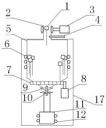
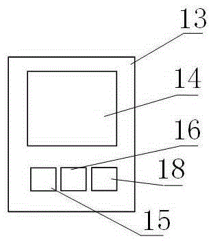
[0055] A crucible 5 is installed on the inner upper end of the shell 17 of the present invention, and an induction coil 6 is wound on the outer wall of the crucible 5; a shut-off valve 9 with a thermocouple 10 is installed at the outlet of the lower end of the crucible 5; A cooling device 12 is installed outside the bottle 11 and the collection bottle 11; the upper mouth of the crucible 5 corresponds to an inlet clip 2 inserted into the needle 1, and a photoelectric sensor 4 and an inlet clip stepping to control the shrinkage of the inlet clip 2 are installed on the inlet clip 2 Motor 3; a gear 7 is fixedly installed on the crucible 5, and the gear 7 is meshed with the shaft of the motor 8; wherein the structure of the inlet clip 2 is: the inlet clip 2 is divided into two parts: the fixed side 24 and the movable side 23, and the fixed side 24 is fixed On the shell 17, a rack 22 is fixedly installed on the movable side 23, and the teeth of the rack 22 are engaged with the teeth ...


PUM


Abstract

A device and method for destroying medical needles belong to the field of medical machinery. The object of the present invention is to provide a medical needle destruction device and method for automatically collecting and destroying the discarded needles generated in the medical work while the medical personnel are performing injection work. A crucible is installed on the inner upper end of the shell of the present invention, and the upper opening of the crucible corresponds to an inlet clip with a needle, and a photoelectric sensor and an inlet clip stepping motor for controlling the shrinkage of the inlet clip are installed on the inlet clip; an induction coil is wound on the outer wall of the crucible; A gear is fixedly installed on the crucible, and the gear meshes with the shaft of the motor; a stop valve with a thermocouple is installed at the outlet of the lower end of the crucible, and a collection bottle is installed at the outlet corresponding to the lower end of the crucible, and a cooling device is installed outside the collection bottle. The invention has the advantages of high efficiency and energy saving, small volume, easy portability, simple, intuitive and easy-to-master operation process, adopts modular design, and is convenient for maintenance.

Description

technical field [0001] The invention belongs to the field of medical machinery. Background technique [0002] Today, in some backward areas, the recovery and disposal of medical needles are still carried out by means of on-site destruction or burial, which easily causes the spread of diseases and pollutes the environment. Especially in African countries, where poverty and backwardness and lack of hygiene knowledge, people often pick up used needles and reuse them, which can easily lead to the spread of AIDS, Ebola and other viruses. At present, most of the existing syringe needle destruction devices are based on scattered collection and centralized destruction. This kind of destruction equipment is generally large in size, high in cost, high in energy consumption, and cannot be moved at will, and is inconvenient to operate. [0003] People have invented some methods to solve the problem of medical needle disposal, and existing needle destruction devices can be roughly summa...

Claims


Application Information

Patent Timeline
Patent Type & Authority Patents(China)
IPC IPC(8): H05B6/24
Inventor 李新波付云博梁亮刘国君吴越刘建芳杨志刚
Owner JILIN UNIV
Why Eureka
Eureka Blog
Learn More