Heat radiation device

A heat sink and heat sink technology, which is applied in heat exchange equipment, indirect heat exchangers, heat exchanger fixation, etc., can solve the problems of increasing the production cost of heat sinks and achieve the effect of reducing production costs

Inactive Publication Date: 2014-12-03
WISTRON CORP +1
View PDF3 Cites 1 Cited by
  • Summary
  • Abstract
  • Description
  • Claims
  • Application Information

AI Technical Summary

Problems solved by technology

In addition, most of the above soldering steps are performed manually, which also increases the manufacturing cost of the heat sink.

Method used


Image

  • Heat radiation device
  • Heat radiation device
  • Heat radiation device

Examples


Embodiment Construction

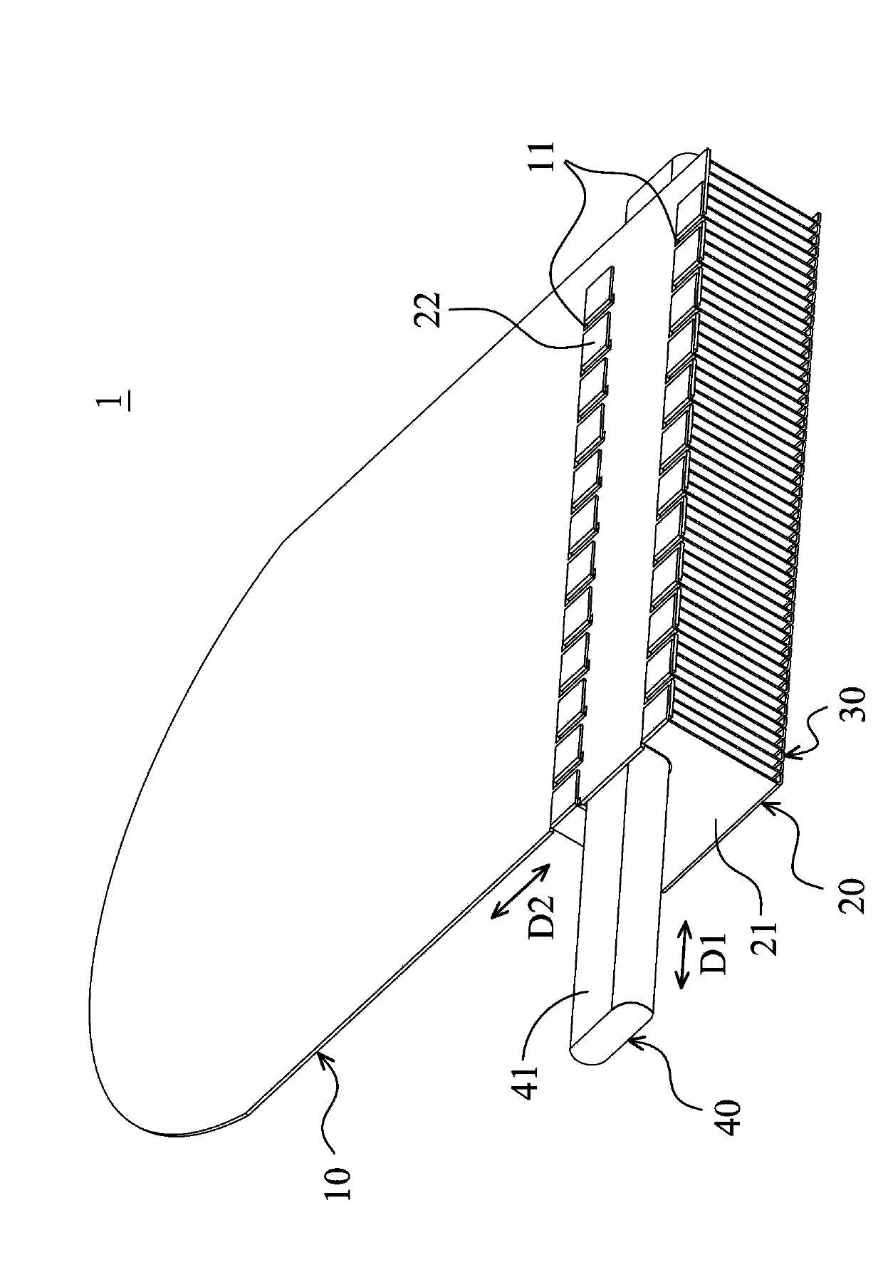
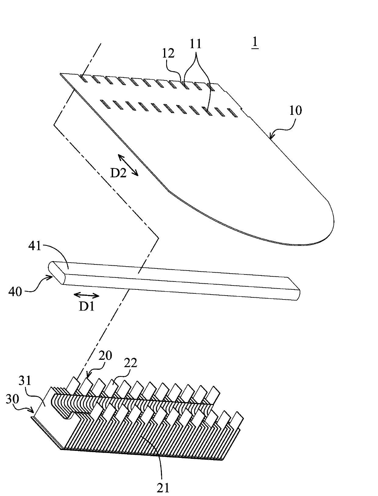
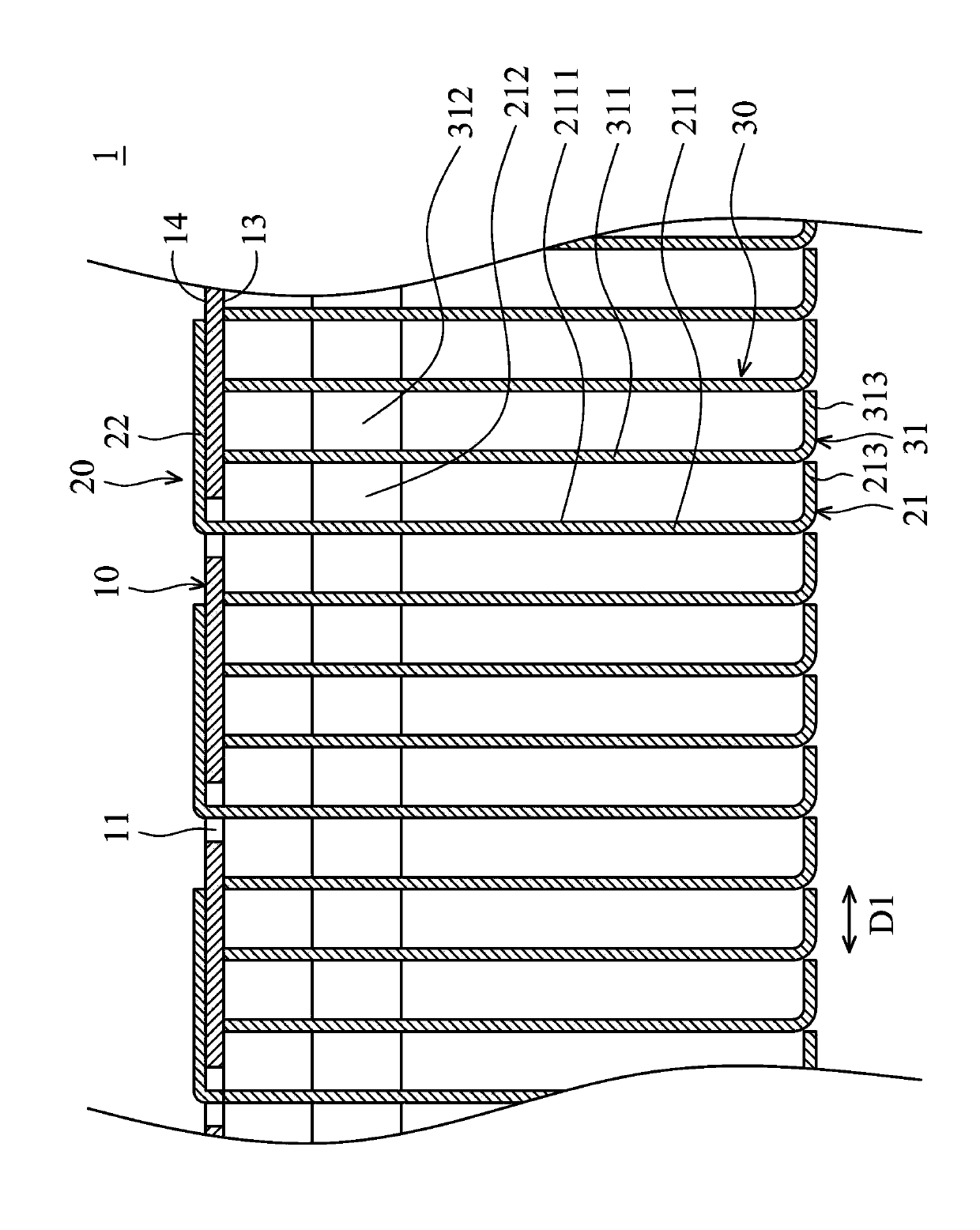
[0051] figure 1 It is a perspective view of the heat sink 1 according to the first embodiment of the present invention. figure 2 It is an exploded view of the heat sink 1 according to the first embodiment of the present invention, wherein the snap-fit ​​piece 22 is in an unbent state. image 3 is a cross-sectional view of the heat sink 1 of the first embodiment of the present invention, Figure 4 is a perspective view of the first fin 20 of the first embodiment of the present invention, Figure 5 It is a perspective view of the second fin 30 of the first embodiment of the present invention. The heat dissipation device 1 can be disposed inside a portable electronic device (not shown) to provide heat dissipation. The heat dissipation device 1 includes a substrate 10 , a plurality of first fins 20 , a plurality of second fins 30 and a heat pipe 40 .

[0052] The substrate 10 can be a printed circuit board or a fixed board inside the electronic device. The material of the fi...


PUM


Abstract

A heat dissipating device includes a substrate, a plurality of fins, and a heat pipe. The substrate has a plurality of retaining holes. Each of the fins includes a heat dissipating sheet and a retaining sheet extended from the heat dissipating sheet and passing through one of the retaining holes. The heat pipe is disposed on the fins.

Description

technical field [0001] The invention mainly relates to a heat dissipation device, especially a heat dissipation device with fins. Background technique [0002] The current manufacturing method of the heat sink generally uses solder paste to fix the fins and heat pipes on the substrate by welding. However, in consideration of environmental protection, the structure of the heat sink needs to be redesigned to reduce the use of solder paste. In addition, most of the above soldering steps are performed manually, which also increases the manufacturing cost of the heat sink. [0003] Therefore, it is necessary to provide a heat dissipation device to solve the above problems. Contents of the invention [0004] In order to solve the shortcomings of the above-mentioned known technologies, the purpose of the present invention is to provide a heat sink, and the heat sink can be assembled without using solder paste. [0005] In order to achieve the above object, the present inventio...

Claims


Application Information

Patent Timeline
Patent Type & Authority Applications(China)
IPC IPC(8): H05K7/20
CPCF28D15/02F28D15/0233F28D15/0275F28F1/30F28F2275/12H01L21/4882H01L23/3672H01L23/427
Inventor 张永利王凯华陈明智
Owner WISTRON CORP
Why Eureka
Try Eureka