Automatic welding rod replacing device for rotor spot welding machine

A spot welding machine and welding rod technology, applied in auxiliary devices, welding equipment, auxiliary welding equipment and other directions, can solve the problems of high requirements for the consistency of welding rod size and increase the labor intensity of workers, so as to ensure consistency and reduce labor. Strength, the effect of improving the degree of automation

Active Publication Date: 2014-12-10
JULI AUTOMATION EQUIP ZHEJIANG CO LTD
View PDF5 Cites 15 Cited by
  • Summary
  • Abstract
  • Description
  • Claims
  • Application Information

AI Technical Summary

Problems solved by technology

Nowadays, the production automation requirements of micro-motor rotors are getting higher and higher. The rotor spot welding machine is an indispensable link in the production of the rotor. In order to ensure the welding quality of the product, the welding rod needs to be replaced frequently. The existing rotor spot welding machine equipment The process of changing welding rods is all done manually, which increases the labor intensity of workers on the one hand, and on the other hand has high requirements for the dimensional consistency of welding rods

Method used


Image

  • Automatic welding rod replacing device for rotor spot welding machine
  • Automatic welding rod replacing device for rotor spot welding machine
  • Automatic welding rod replacing device for rotor spot welding machine

Examples


Embodiment Construction

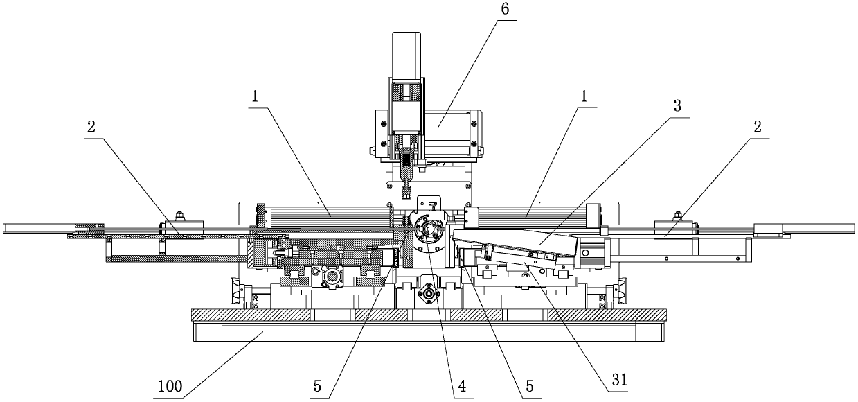
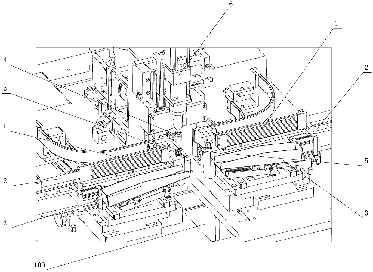
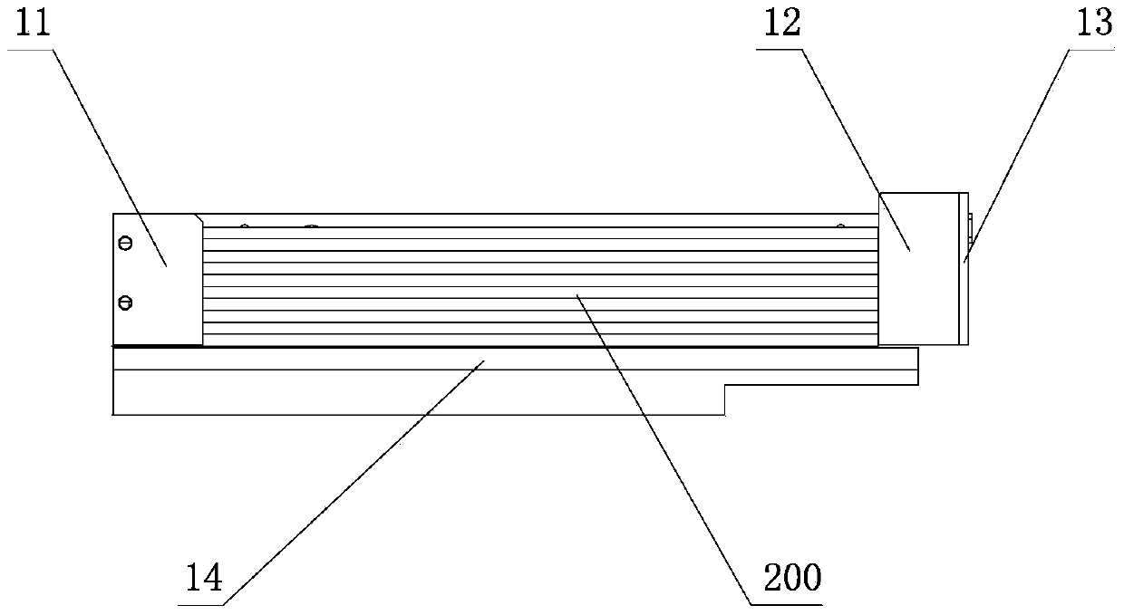
[0023] Refer to attached picture.

[0024] The automatic welding rod changing device of the rotor spot welding machine of the present invention comprises a frame 100, which is provided with a new welding rod storage folder 1, a welding rod pusher mechanism 2, an old welding rod receiving device 3, and a welding rod positioning Device 4, welding rod clamping seat 5 and tightening device 6, the new welding rod storage folder 1 is used to store spare welding rods, the welding rod pusher mechanism 2 is used to push the welding rod to the position required for welding, and the old welding rod is connected The material device 3 is used to collect incompletely used welding rods (discarded welding rods) to keep the working environment of the device clean and tidy. The welding rod positioning device 4 is used to position the welding rods pushed out by the welding rod pusher mechanism 2. The end face is in a suitable position for welding. The welding rod clamping seat 5 is used to clamp...


PUM


Abstract

The invention provides an automatic welding rod replacing device for a rotor spot welding machine. The automatic welding rod replacing device comprises a new welding rod storage clamp, a welding rod push rod mechanism, a used welding rod receiving device, a welding rod positioning device, a welding rod clamping seat and a tightening device. The new welding rod storage clamp is used for storing standby welding rods; the welding rod push rod mechanism is used for pushing welding rods to a welding required position; the used welding rod receiving device is used for collecting incompletely used welding rods; the welding rod positioning device is used for positioning welding rods; the welding rod clamping seat is used for clamping the welding rods during welding to prevent the welding rods from slipping; the tightening device is used for tightening or loosening a fixing device on the welding rod clamping seat. By the automatic welding rod replacing device, the problems of demounting of the used welding rods, storage and discharging of new welding rods, positioning and clamping of the new welding rods, spot welding count setting and automatic control of the whole process are solved, automatic replacing and clamping of the welding rods can be realized without manual intervention, automation degree is greatly improved, labor intensity is relieved, uniformity in clamping of the welding rods can be guaranteed, and production efficiency is improved.

Description

technical field [0001] The invention relates to a rotor spot welder. Background technique [0002] The rotor spot welding machine is used for the welding of the rotor commutator and the wire wrap winding in the micro-motor industry. It belongs to the field of micro-motor manufacturing and is a professional automatic motor manufacturing production equipment. [0003] With the development and needs of society, micro motors have been widely used in household appliances, electric tools, automobiles and other fields. Nowadays, the production automation requirements of micro-motor rotors are getting higher and higher. The rotor spot welding machine is an indispensable link in the production of the rotor. In order to ensure the welding quality of the product, the welding rod needs to be replaced frequently. The existing rotor spot welding machine equipment The process of changing the welding rods is all done manually, which increases the labor intensity of the workers on the one h...

Claims


Application Information

Patent Timeline
Patent Type & Authority Applications(China)
IPC IPC(8): B23K37/00
CPCB23K37/00B23K37/0443
Inventor 章日平吴应德
Owner JULI AUTOMATION EQUIP ZHEJIANG CO LTD
Why Eureka
Try Eureka