Novel hot melting cement 3D printing head

A print head and hot-melt technology, applied in the field of 3D printing, can solve problems such as poor fluidity, difficult molding, and high temperature

Active Publication Date: 2014-12-10
深圳市三帝梦工场科技开发有限公司 +2
View PDF5 Cites 9 Cited by
  • Summary
  • Abstract
  • Description
  • Claims
  • Application Information

AI Technical Summary

Problems solved by technology

However, at present, the main materials of 3D printing are chemical materials such as ABS and nylon, while building mate

Method used


Image

  • Novel hot melting cement 3D printing head
  • Novel hot melting cement 3D printing head
  • Novel hot melting cement 3D printing head

Examples


Embodiment 1

[0029] This embodiment provides a hot-melt cement 3D printing head. The hot-melt cement 3D printing head is mainly used for 3D printing of cement, and can also be used for high-precision 3D printing of high-viscosity, very-temperature materials such as chocolate and butter cake.

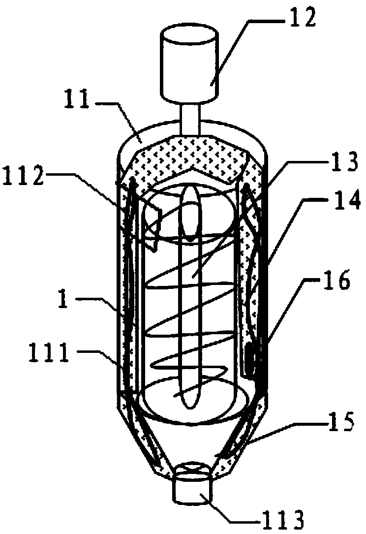
[0030] Please refer to figure 1 , the hot melt cement 3D printing head includes a hot material conveying device 1 .

[0031] The hot material conveying device 1 includes a tank body 11 , a motor 12 , a worm 13 and a heating resistor 14 .

[0032] The tank body 11 is provided with an interlayer 111, that is, the tank body is composed of two layers of inner and outer walls with a certain gap formed in the middle, and the inside of the tank body 11 is a cylindrical cavity. Such as figure 1 In the direction shown, the upper end of the tank body 11 is provided with a feed port 112, which is used to import the pre-prepared printing materials; the bottom end of the tank body 11 is in the shape of an inver...

Embodiment 2

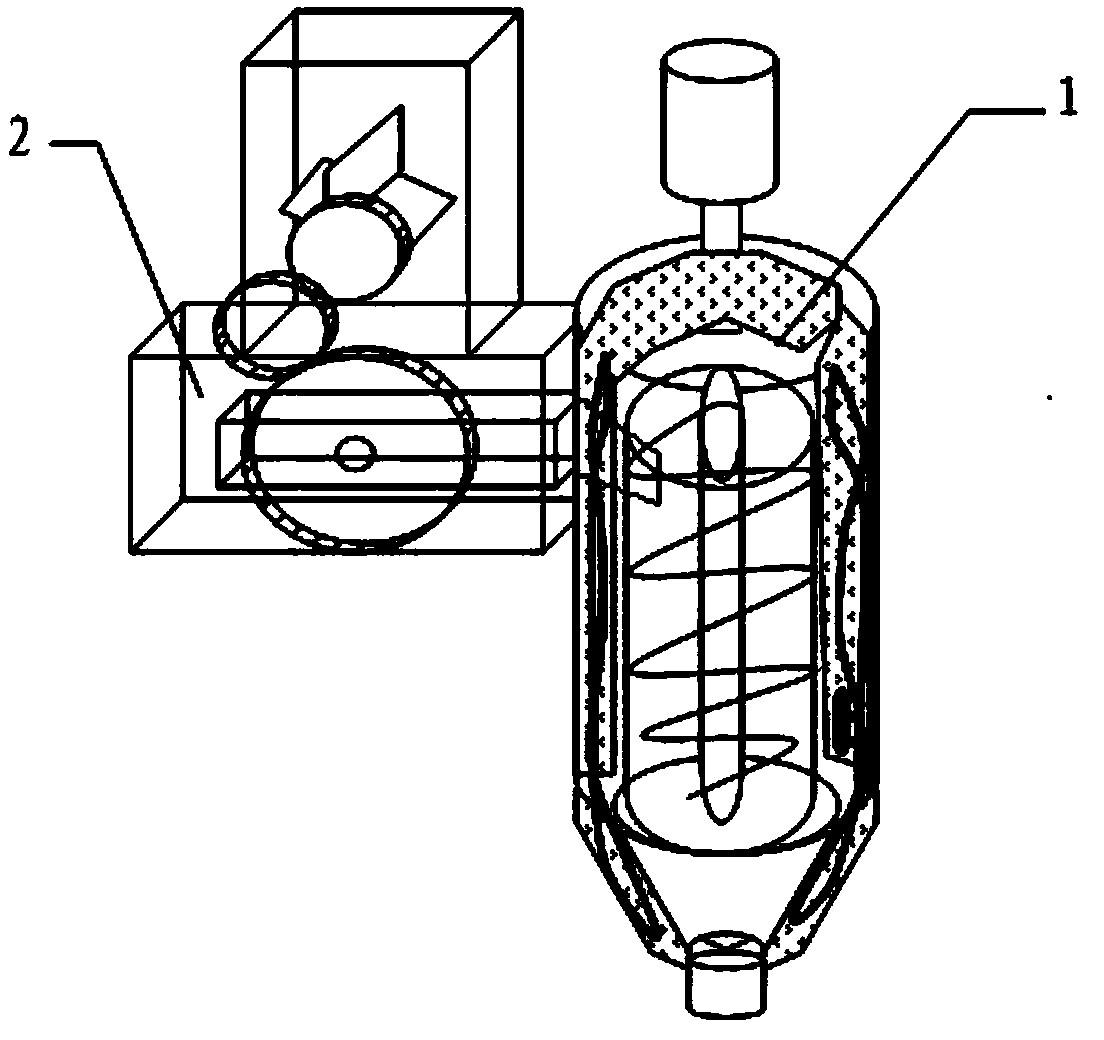
[0043] In this embodiment, a cold material conveying device 2 is added on the basis of the above embodiments. The cold material conveying device 2 can conveniently, accurately and effectively supply materials to the hot material conveying device 1, improving printing efficiency.

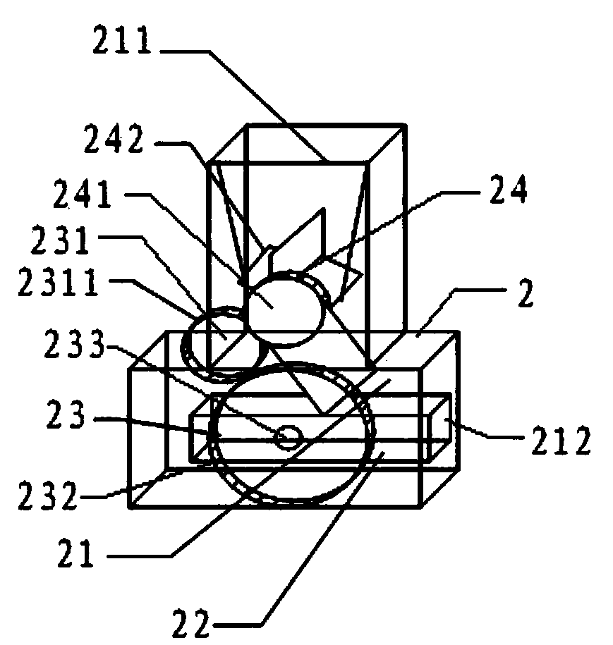
[0044] Please refer to figure 2 with image 3 , The cold material conveying device includes a cold material bin 21 , a push piston 22 and a driving member 23 .

[0045] The cold material bin 21 is used to accommodate the cold material, such as figure 2 In the direction shown, the top of the cold material bin 21 is provided with a feed port 211, the feed port 211 is funnel-shaped, and the right side of the lower end is provided with a discharge port 212, and the discharge port 212 is connected with the feed port 111 of the hot material conveying device 1 , connect the cold material conveying device 2 with the hot material conveying device 1 to realize material supply.

[0046] The push piston 22 ...


PUM


Abstract

The invention relates to a novel hot melting cement 3D printing head. The novel hot melting cement 3D printing head comprises a hot material conveying device, wherein the hot material conveying device comprises a tank body, a hot material motor, a worm rod and a heating resistor; the tank body is a cylindrical cavity; a shell interlayer made of a heat insulating material is arranged outside the tank body; a feed port is formed in the side surface of the upper end of the tank body; a conical nozzle is arranged at the lower end of the tank body; the hot material motor is fixed at the top end of the tank body, and is connected with a feeding worm rod through a coupling; one end of the worm rod is connected with the motor, a rotating shaft and the coupling, and is fixed at the upper end of the tank body by using a bearing; spiral blades are arranged on the worm rod; and the heating resistor is fixed in the interlayer of the tank body. The novel hot melting cement 3D printing head further comprises a cold material conveying device, wherein the cold material conveying device comprises a cold material bin and a piston pushing device; the cold material bin is provided with a rotary feeding valve; the rotary feeding valve is in engaged connection with a cold material motor gear; and the piston pushing device consists of a concave wheel and a pushing piston, is fixed at the lower part of the cold material bin, is engaged to the cold material motor gear, and realizes the piston type pushing of a cold material to a hot material feed port.

Description

technical field [0001] The invention relates to the technical field of 3D printing, in particular to a novel hot-melt cement 3D printing head. [0002] Background technique [0003] 3D printing technology is a rapid prototyping manufacturing technology that has developed rapidly at home and abroad in recent years. It has fast forming speed, cheap equipment, low operation and maintenance costs, and can be personalized and creative. It is a manufacturing method in the new era of big data cloud computing. At present, it has been widely used in various engineering fields of modern society such as machinery, electronics, aircraft, biomanufacturing, pharmaceuticals, micro-electromechanical, construction, etc., showing a broad market prospect. However, at present, the main materials for 3D printing are chemical materials such as ABS and nylon, while building materials such as cement have high temperature, poor fluidity, and 3D printing that is not easy to form has not been applied...

Claims


Application Information

Patent Timeline
IPC IPC(8): B28B1/24B28B17/00
CPCB28B1/24B28B17/00
Inventor 文进希
Owner 深圳市三帝梦工场科技开发有限公司
Why Eureka
Try Eureka