Film squeeze dehydrator

A dehydrator and film technology, applied in the direction of presses, manufacturing tools, etc., can solve the problems of easy sticking into a lump, high energy consumption, reduced pelletizing effect, etc., to reduce energy consumption, increase extrusion force, and improve extrusion The effect of dehydration

Active Publication Date: 2014-12-10
ZHANGJIAGANG BEISIJIA MACHINERY
View PDF7 Cites 4 Cited by
  • Summary
  • Abstract
  • Description
  • Claims
  • Application Information

AI Technical Summary

Problems solved by technology

[0005] The main disadvantages of the above structure are: the working efficiency of the film squeezing dehydrator is relatively low, the energy consumption is high, and the effect of squeezing and dehydrating is not ideal. During the working process of the film squeezing dehydrator, the heater needs to be positioned at the plasticizing section The material in the barrel is heated to ensure that the material in the barrel of the plasticizing section can always be in a molten and plasticized state, so that the molten and plasticized material can be extruded through the extrusion hole on the discharge template; in addition, The granular materials that fall into and accumulate in the storage box are in a molten and plasticized state, so they are easy to stick together into a lump, which greatly reduces the effect of pelletizing

Method used


Image

  • Film squeeze dehydrator
  • Film squeeze dehydrator
  • Film squeeze dehydrator

Examples


Embodiment Construction

[0022] The technical solutions of the present invention will be further described in detail below in conjunction with the accompanying drawings and preferred embodiments.

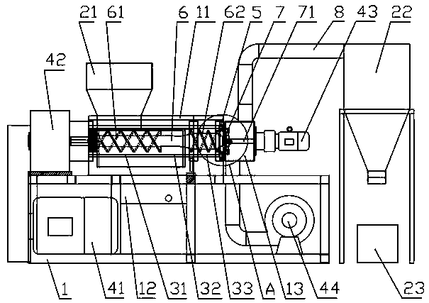
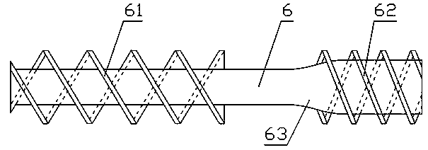
[0023] Such as figure 1 , figure 2 As shown, the film squeezing dehydrator of the present invention includes: a machine barrel 3 arranged on the machine base 1, and a casing 11 covering the machine barrel 3 is arranged on the periphery of the machine barrel 3, and the machine The barrel is composed of a feeding section barrel 31, a compression section barrel 32 and a plasticizing section barrel 33, and a feed hopper 21 communicating with the barrel 3 is arranged on the barrel of the feeding section barrel 31; the screw rod 6 The screw rod 6 inserted into the barrel 31 of the feeding section is provided with a first threaded section 61, and the screw 6 located in the barrel 32 of the compression section is a polished rod, which extends into the plasticizing section machine. The screw rod 6 in the cylinder...


PUM


Abstract

The invention discloses a film squeeze dehydrator. A machine barrel and a housing are arranged on a stand; the machine barrel consists of a feed section machine barrel, a compression section machine barrel and a plastifying section machine barrel; a feed hopper is arranged on the feed section machine barrel; a screw rod is inserted in the machine barrel; a first thread section is arranged on the screw rod extending in the feed section machine barrel; the screw rod in the compression section machine barrel is a polish rod; a second thread section is arranged on the screw rod extending in the plastifying section machine barrel; a first driving device is arranged at the outer side of the feed section machine barrel; a discharge template covers in an opening of the plastifying section machine barrel; a cutting device driven by a second driving device is arranged at the outer side of the discharge template; conical drain holes are formed in the walls of the feed section machine barrel and the compression section machine barrel; the first and second thread sections are both double threads; the thread pitch of the first thread section is greater than the thread pitch of the second thread section; and a material stop box with a conveying device is arranged at the outer side of the plastifying section machine barrel. The film squeeze dehydrator has the advantages of good squeeze dehydration and granulation effects, high working efficiency and low energy consumption.

Description

technical field [0001] The invention relates to the technical field of plastic recycling, in particular to a film squeezing and dehydrating machine. Background technique [0002] As the application range of plastic products becomes wider and wider, there are more and more waste plastics. Waste plastics are not easy to rot. If they are not handled properly, they will not only waste resources, but also seriously affect people's living environment and endanger people's health. , so it is necessary to recycle and reuse waste plastics. [0003] The film squeezing dehydrator is mainly used to recycle waste films, plastic bags, woven bags and other membranous waste plastics. By squeezing, dehydrating and cutting the broken and cleaned materials, i.e. membranous waste plastics, into granular materials, there is It is beneficial to the recycling of film-like waste plastics. [0004] Patent No. 201120480400.9 discloses a film squeezing dehydrator in the Chinese invention patent lite...

Claims


Application Information

Patent Timeline
Patent Type & Authority Applications(China)
IPC IPC(8): B29B9/06B29C47/08B30B9/14
Inventor 李平心
Owner ZHANGJIAGANG BEISIJIA MACHINERY
Why Eureka
Try Eureka