Device for forming winding type bell and spigot joint

A technology for forming equipment and socket joints, which is applied in the field of forming equipment for winding socket joints, can solve the problems of high cost and complex structure of winding forming equipment, and achieve the effects of low cost, low thermal conductivity and high stability

Active Publication Date: 2014-12-10
ZHANGJIAGANG XIEXIN MACHINERY
View PDF4 Cites 4 Cited by
  • Summary
  • Abstract
  • Description
  • Claims
  • Application Information

AI Technical Summary

Problems solved by technology

But at present, the cost of winding forming equipment is relatively high, and the structure is relatively complicated.

Method used


Image

  • Device for forming winding type bell and spigot joint
  • Device for forming winding type bell and spigot joint
  • Device for forming winding type bell and spigot joint

Examples


Embodiment Construction

[0019] The forming equipment of a twisted socket joint according to the present invention will be further described in detail through specific embodiments below.

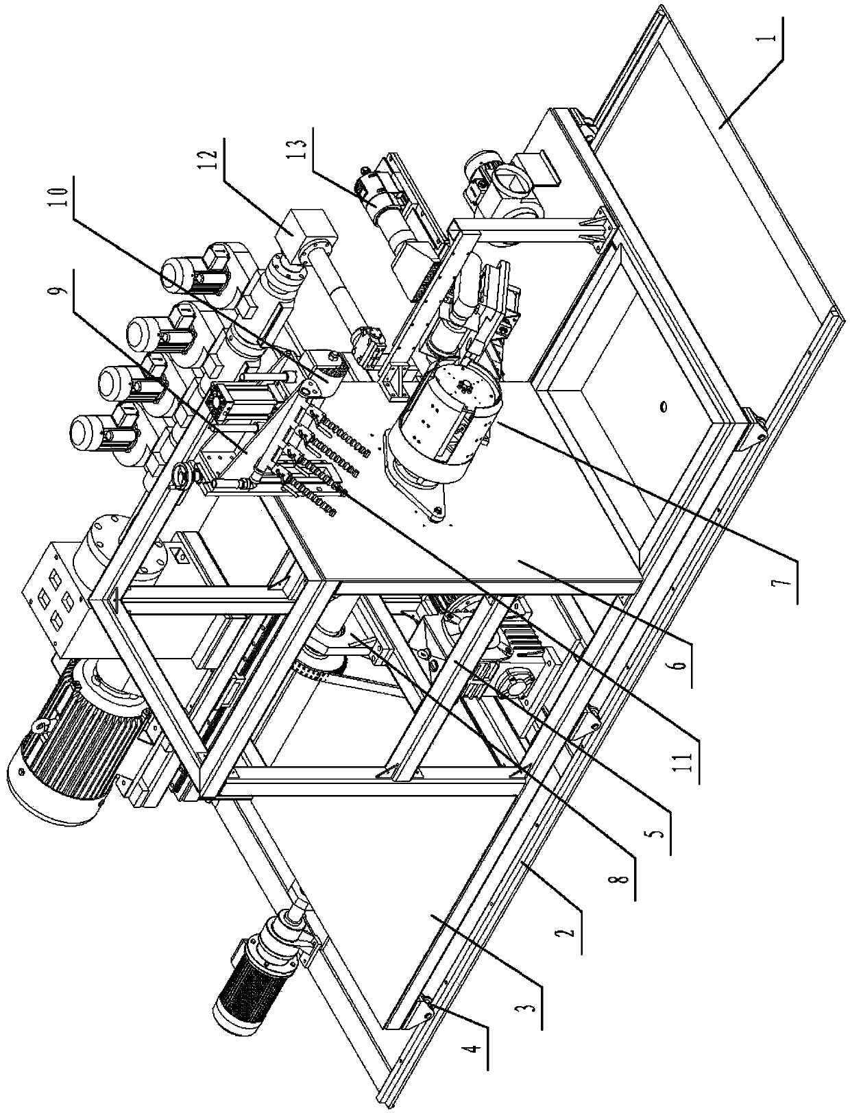
[0020] Such as figure 1 As shown, a forming equipment for winding socket joints includes a fixed frame 1, on which a track 2 is arranged, on which a movable frame 3 that can move forward and backward is movably arranged, and the bottom of the movable frame 3 A pulley 4 matched with the track 2 is provided, a frame mold frame 5 is provided on one side of the movable frame 3, a mounting plate 6 is provided at the front end of the mold frame 5, and a mold 7 is provided on the front end surface of the mounting plate 6, and the mold 7 and the rail 2. Arranged in parallel, a mold driving mechanism 8 is arranged in the mold frame 5, and the mold driving mechanism 8 passes through the mounting plate 6 to connect with the mold 7. The mold frame 5 is also provided with a pressure roller frame 9 that can move up and down, and ...


PUM


Abstract

The invention relates to a device for forming a winding type bell and spigot joint. The device for forming the winding type bell and spigot joint comprises a fixing rack, wherein a track is arranged on the fixing rack; a movable rack capable of moving back and forth is movably arranged on the fixing rack; a pulley matched with the track is arranged at the bottom of the movable rack; a framework-shaped die rack is arranged on one side of the movable rack; a mounting plate is arranged at the front end of the die rack; a die is arranged on the front end surface of the mounting plate; the die and the track are parallel to each other; a die driving mechanism is arranged in the die rack; the die driving mechanism passes through the mounting plate so as to be connected with the die; a press wheel rack capable of moving up and down is also arranged on the die rack; a press wheel is arranged at the bottom of the press wheel rack; a rolling and milling cutter is arranged on the outer side of the press wheel rack; the position of the press wheel rack is arranged above the die; an extruder capable of moving back and forth relative to the die is movably arranged on the other side of the movable rack; an outlet of the extruder corresponds to the die; a hot air gun is arranged below the outlet of the extruder. The device for forming the winding type bell and spigot joint is suitable for producing winding pipes.

Description

technical field [0001] The invention relates to the technical field of coiled pipe production, in particular to a forming device for a coiled socket joint. Background technique [0002] Existing spiral winding plastic pipes can be divided into specific product forms such as hollow wall winding pipes, carat pipes, steel belt reinforced winding pipes, internal rib reinforced winding pipes, and plastic steel winding pipes according to the different materials used in winding molding. Because of its high ring stiffness, it is widely used in drainage, low-pressure water supply and other occasions. The connection methods of pipelines mainly include electric fusion belt connection, heat shrink sleeve connection, electric fusion socket connection, socket sealing ring connection, clamp connection and other methods. Among them, the electric fusion belt connection and the thermoplastic sleeve connection are widely used due to their low cost, but the construction environment and technol...

Claims


Application Information

Patent Timeline
IPC IPC(8): B29C53/56B29C53/80
Inventor 陆宇航孙德金
Owner ZHANGJIAGANG XIEXIN MACHINERY
Why Eureka
Try Eureka