
Die-cutting upper cutting die and manufacturing method thereof

A manufacturing method and die-cutting technology, which are used in box manufacturing operations, container manufacturing machinery, rigid/semi-rigid container manufacturing, etc., can solve the horizontal and vertical errors of the indentation line, which have not been solved, and the box shape is skewed, etc. problems, to achieve the effect of improving production efficiency, ensuring accuracy, and reducing processing links

Inactive Publication Date: 2014-12-10
HUIXINLEI DIE CUTTER TECH CO LTD
View PDF8 Cites 5 Cited by
  • Summary
  • Abstract
  • Description
  • Claims
  • Application Information

AI Technical Summary

Problems solved by technology

[0003] Regardless of whether manual molding or molding is used, the common problem is that the indentation line in the peripheral roll is manually set directly on the die-cutting die carrier plate, and it is inevitable that the indentation line will There are errors in the horizontal and vertical directions, and the indentation formed by the indentation line on the cut object plays a very important role in whether the shape of the box meets the standard when the cut object is finally folded into a box, even if it is As long as the relative direction of the horizontal indentation line or \ and the vertical indentation line is off by a few wires, the final box shape will be skewed, which is not allowed
Therefore, setting the indentation line in a standard way so that the relative positions of the horizontal indentation line and the longitudinal indentation line are not different from the design standard is a problem that the printing and packaging industry has long wanted to solve but has not solved. This problem has been plaguing the entire printing and packaging industry. industry, the problem has remained unsolved for decades

Method used


Image

  • Die-cutting upper cutting die and manufacturing method thereof
  • Die-cutting upper cutting die and manufacturing method thereof
  • Die-cutting upper cutting die and manufacturing method thereof

Examples


Embodiment Construction

[0023] In the description of the present invention, it should be understood that the orientations or positional relationships indicated by "upper", "lower", "left", "right", etc. in the terms are based on the orientation or positional relationships shown in the drawings, and are only In order to facilitate the description of the present invention and simplify the description, it does not indicate or imply that the device or element referred to must have a specific orientation, be constructed and operated in a specific orientation, and thus should not be construed as limiting the present invention. In addition, the terms "first" and "second" are used for descriptive purposes only, and should not be understood as indicating or implying relative importance. In the description of the present invention, it should be noted that unless otherwise specified and limited, the term "connection" should be understood in a broad sense, for example, it can be a fixed connection, a detachable ...


PUM


Abstract

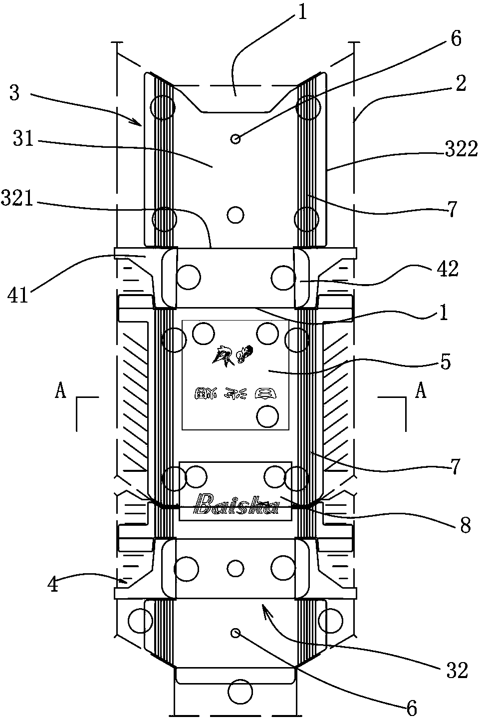
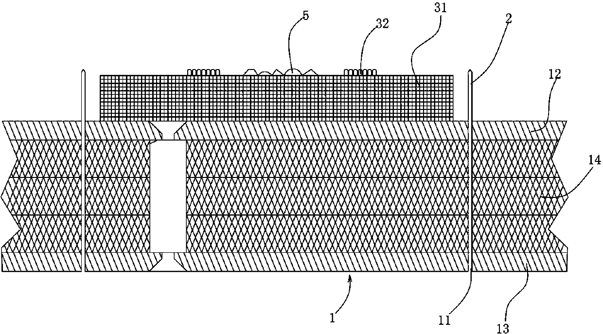
The invention discloses a die-cutting upper cutting die and a manufacturing method of the die-cutting upper cutting die. The upper cutting die comprises a die-cutting upper cutting die carrier plate, wherein forming blades used for forming the periphery of an object to be cut are embedded into the die-cutting upper cutting die carrier plate, at least a creasing line die block used for generating creases on the object to be cut and angle die cutters are arranged in a peripheral encirclement defined by the forming blades, the creasing line die block comprises a metal substrate with a defined shape, creasing lines directly machined on the metal substrate are arranged on the surface of the metal substrate, and protrude out of the metal substrate for the preset height and in the preset shape, and the metal substrate is fixedly connected with the die-cutting upper cutting die carrier plate through fasteners. The die-cutting upper cutting die and the manufacturing method of the die-cutting upper cutting die have the advantage that relative positions of transverse creasing lines and longitudinal creasing lines exactly meet the design standard.

Description

technical field [0001]    The invention relates to a die-cutting upper die used in the printing and packaging industry and a manufacturing method thereof, in particular to a die-cutting upper die used for making cigarette boxes and a manufacturing method thereof. Background technique [0002] Existing die-cutting upper dies used in the printing and packaging industry generally include a die-cutting upper die carrier plate and various forming blades inlaid on the die-cutting upper die carrier plate. These forming blades can form peripheral rolls, knuckles And\or rounded corner dies, there are also creasing lines arranged horizontally and vertically for creating creases in the outer volume, of course, according to needs, it can also be set in the outer volume for forming on the object A concave-convex stamper with a predetermined concave-convex shape, embossed lines for forming predetermined stripes on the object and / or text and / or patterns used to form anti-counterfeiting ef...

Claims


Application Information

Patent Timeline
Patent Type & Authority Applications(China)
IPC IPC(8): B31B1/25B31B1/14B31B50/25
Inventor 蒋和健
Owner HUIXINLEI DIE CUTTER TECH CO LTD
Learn More