Rapid vortex-free neutralization device for electroplating wastewater

A technology of electroplating wastewater and vortex, which is applied in metallurgical wastewater treatment, neutralization water/sewage treatment, etc., can solve the problems of slow neutralization speed, low efficiency, affecting neutralization speed and neutralization effect, etc., and achieve fast neutralization Handling, increasing the reaction rate, avoiding the effects of vortexing

Inactive Publication Date: 2014-12-10
DANYANG CITY XINGUANG ELECTRON
View PDF3 Cites 2 Cited by
  • Summary
  • Abstract
  • Description
  • Claims
  • Application Information

AI Technical Summary

Problems solved by technology

The existing neutralization treatment method adopts the mode of artificial neutralization treatment, which has the disadvantages of slow neutralization speed and low efficiency; Chinese patent CN 203807221 U discloses a rapid neutralization device for electroplating wastewater (such as figure 1 shown), including a neutralization tank, a hollow stirring shaft, a hollow shaft reducer, a rotary joint, a booster pump, and a liquid filling tank. A hollow shaft reducer is installed on the neutralizing tank, and a hollow stirring shaft is installed On the hollow shaft reducer, the hollow stirring shaft is connected to the liquid feeding pipe II through a rotary joint, and the hollow stirring shaft is equipped with hollow stirring paddle I, hollow stirring paddle II and hollow stirring paddle III. The stirring paddle Ⅰ, the hollow stirring paddle Ⅱ and the hollow stirring paddle Ⅲ are equipped with liquid distribution holes; this utility model realizes the rapid and efficient neutralization treatment of electroplating wastewater
However, the stirring blade of this utility model is easy to form a spiral vortex in the neutralization tank during use, which seriously affects the neutralization speed and neutralization effect, prolongs the treatment time of electroplating wastewater, and reduces the treatment efficiency of electroplating wastewater, so it needs to be improved urgently

Method used


Image

  • Rapid vortex-free neutralization device for electroplating wastewater
  • Rapid vortex-free neutralization device for electroplating wastewater

Examples


Embodiment Construction

[0012] The technical solution of this patent will be further described in detail below in conjunction with specific embodiments.

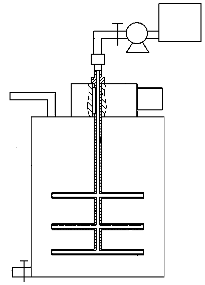
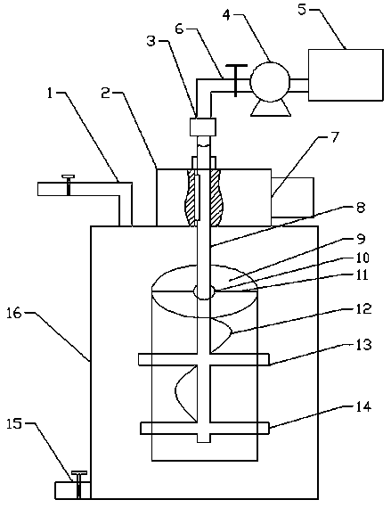
[0013] see figure 2 , a vortex-free rapid neutralization device for electroplating wastewater, including a neutralization tank 16, a hollow stirring shaft 8, a sleeve 9, a hollow shaft type reducer 7, a rotary joint 3, a booster pump 4 and a liquid filling tank 5, in which A hollow shaft type reducer 7 is installed above the tank 16, and the hollow stirring shaft 8 is installed on the hollow shaft type reducer 7. The upper end of the hollow stirring shaft 8 is connected to the liquid feeding pipe 6 through the rotary joint 3, and the liquid feeding pipe 6 is connected to the increasing On the pressure pump 4, the booster pump 4 communicates with the filling tank 5, and a valve is provided on the filling pipe 6; Both the liquid pipe 1 and the discharge pipe 15 are provided with control valves; the lower end of the hollow stirring shaft 9 extends v...


PUM


Abstract

The invention discloses a rapid vortex-free neutralization device for electroplating wastewater. The rapid vortex-free neutralization device comprises a neutralization tank, a hollow stirring shaft, a sleeve, a hollow shaft type speed reducer, a rotating connector, a pressurizing pump and a liquid adding tank, wherein the hollow shaft type speed reducer is mounted above the neutralization tank; the hollow stirring shaft is mounted on the hollow shaft type speed reducer; the upper end of the hollow stirring shaft is connected with a liquid adding tube through the rotating connector; the liquid adding tube is connected with the pressurizing pump; the pressurizing pump is communicated with the liquid adding tank. When the rapid vortex-free neutralization device is used for stirring, the electroplating wastewater is fed into the sleeve from the lower end of the sleeve and further flows out from the upper end of the sleeve due to adoption of spiral blades and the sleeve, so that vertical counter circulation flow is formed, the phenomenon of vortex caused by rotating stirring is avoided, the reaction velocity is also improved, and rapid neutralization treatment is achieved.

Description

technical field [0001] The invention relates to the field of electroplating wastewater treatment, in particular to a vortex-free rapid neutralization device for electroplating wastewater. Background technique [0002] The sources of electroplating wastewater are generally: (1) cleaning water for plating parts; (2) waste electroplating solution; (3) other wastewater, including washing the floor of the workshop, washing water for scrubbing plates, condensed water from ventilation equipment, and leakage of plating tanks. Or various tank liquids and drainages of "running, popping, dripping, and leaking" caused by improper operation and management; (4) Equipment cooling water, which has not been polluted except for the temperature rise during use. The water quality and quantity of electroplating wastewater are related to the process conditions of electroplating production, production load, operation management and water use methods and other factors. The water quality of ele...

Claims


Application Information

Patent Timeline
Patent Type & Authority Applications(China)
IPC IPC(8): C02F1/66C02F103/16
Inventor 封毅
Owner DANYANG CITY XINGUANG ELECTRON
Why Eureka
Try Eureka