Cantilever frame of tool type profile steel cantilever scaffold
A cantilevered scaffolding and tool-type technology, which is applied to the accessories of the scaffolding, the scaffolding supported by the building structure, the support of the building structure, etc. The process is cumbersome and other problems to achieve the effect of reducing safety risks, improving operation safety and solid structure
- Summary
- Abstract
- Description
- Claims
- Application Information
AI Technical Summary
Problems solved by technology
Method used
Image

Examples
Embodiment 1
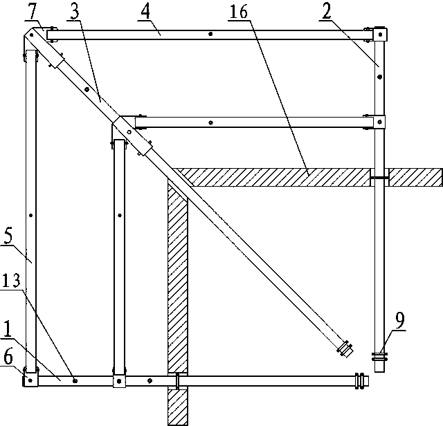
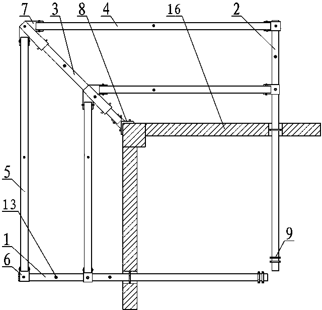
[0033] Such as figure 1 As shown, the cantilever frame of the tool-type steel cantilevered scaffolding includes a support structure and a bottom protection plate, wherein the bottom protection plate is fixed above the support structure, and the support structure includes a plurality of transverse cantilevered steel beams 1, a plurality of Longitudinal cantilevered steel beams 2 arranged vertically, and corner cantilevered steel beams 3 arranged at corners of the building. The horizontal cantilevered steel beam 1, the longitudinal cantilevered steel beam 2 and the corner cantilevered steel beam 3 of this embodiment are all fixed on the building floor and cantilevered after crossing the building edge beam 16. In order to prevent the horizontal cantilevered steel beam from 1 and the longitudinal cantilevered steel beam 2 are offset. In this embodiment, U-shaped anchor bolts are used to strengthen and fix the transverse cantilevered steel beam 1 and the longitudinal cantilevered s...
Embodiment 2
[0036] This embodiment makes the following further limitations on the basis of Embodiment 1: the extension line of the central axis of the horizontal connecting beam 4 and the longitudinal connecting beam 5 in this embodiment and the extension line of the central axis of the corner cantilevered steel beam 3 The included angles are all 45°.
Embodiment 3
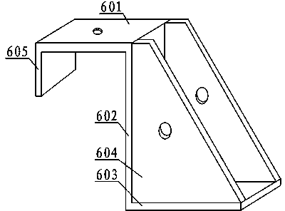
[0038] This embodiment makes the following further limitations on the basis of Embodiment 2: the transverse cantilevered steel beam 1 and the longitudinal cantilevered steel beam 2 of this embodiment are provided with right-angled connectors 6, wherein the transverse connecting beam 4 passes through It is connected to the longitudinal cantilevered steel beam 2 on the right-angled connector 6 , and the longitudinal connecting beam 5 is connected to the transverse cantilevered steel beam 1 by being connected on the right-angled connector 6 . The corner cantilevered steel beam 3 is provided with a corner connector 7, and the horizontal connecting beam 4 and the longitudinal connecting beam 5 connected with the corner cantilevered steel beam 3 are connected to the corner cantilevered steel beam through the corner connector 7. 3 connections.
PUM
 Abstract
Description
Claims
Application Information