A keyhole protective cover device used on an electronic door lock

An electronic door lock and protective cover technology, applied in the field of electronic locks, can solve the problems of illegal opening of the lock body, easy damage to the key hole, illegal configuration of mechanical key molds, etc., and achieves the effect of simple structure and principle, and preventing malicious damage.

Active Publication Date: 2016-07-06
WUHAN PULINGUANGTONG TECH
View PDF6 Cites 0 Cited by
  • Summary
  • Abstract
  • Description
  • Claims
  • Application Information

AI Technical Summary

Problems solved by technology

However, in this patent, there is a problem with the self-protection function of the CNC lock cylinder. The keyhole is easily damaged, such as pouring super glue into the keyhole, or inserting a toothpick into the keyhole, etc.; and daily technical means can also be used to pass through the keyhole. Illegally configure the mechanical key mold so that the lock body can be opened illegally when the electronic lock fails

Method used


Image

  • A keyhole protective cover device used on an electronic door lock
  • A keyhole protective cover device used on an electronic door lock
  • A keyhole protective cover device used on an electronic door lock

Examples


Embodiment 1

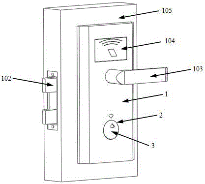
[0025] Example one, such as figure 1 As shown, an electronic door lock according to an embodiment of the present invention is installed with a key cover protection device as a whole structure diagram; the electronic door lock consists of a lock body panel 1, a key hole 2, a bolt 102, a handle 103, a card swiping controller 104, and The mechanical lock core 106 located in the key hole is jointly constituted and installed on the door body 105. It can be seen that the key cover 3 covers the key hole.

[0026] It can be understood that the authorization method of the electronic door lock can also include other structures, such as adding fingerprint recognition authorization, Bluetooth connection, password keyboard, iris recognition, voice recognition, etc. The above methods are commonly used in existing electronic door locks The authorization recognition mode does not limit the present invention.

[0027] It can be understood that the electronic door lock can also include other struct...

Embodiment 2

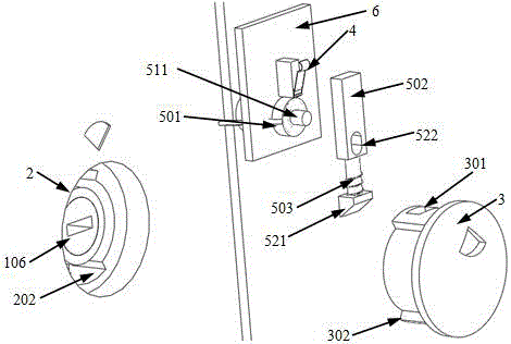
[0042] The second embodiment, the difference between this embodiment and the first embodiment is that the electric control device is a miniature electromagnet 504 whose bearing extends after power-on, and the bearing can be retracted automatically after power-off. The front end of the bearing can be connected to the key cover. The hook 541 matched with the card slot 301; the key cover is rotated into the key hole and snapped with the front end of the bearing; Image 6 Shown is the exploded structure diagram of the electronic control device, the key cover and the key hole.

[0043] It can be seen that the limiting protrusion 302 on the key cover in the figure is screwed into the limiting slot 202 of the key hole, and the card slot 301 cooperates with the hook 541 at the front end of the electromagnet bearing so that the key cover is stuck. Unable to open.

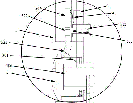
[0044] Such as Figure 7 Shown in is the cross-sectional structure diagram when the electronic control device is used in conjun...

Embodiment 3

[0048] The third embodiment, the difference between this embodiment and the second embodiment is that the electric control device is a miniature electromagnet 505 whose bearing extends after power on and the bearing can retract automatically after power off.

[0049] In the daily state, the electromagnet bearing remains retracted; when the key cover is pressed or rotated, the induction switch will be triggered; at this time, if the electronic controller is normal, the electromagnet 505 will be energized, and the bearing will extend and snap into The card slot 301 on the key cover prevents the key cover from rotating and opening; if the electronic controller fails and the electromagnet 505 does not work, continue to rotate the key cover to open. Such as Figure 8 It is a schematic diagram of the electronic control device and the key cover of this structure, Picture 9 The cross-sectional structure view of the electronic control device and the key cover with this structure closed.


PUM


Abstract

A keyhole protective cover device used on an electronic door lock, the device includes a key hole 2 located on a lock body panel 1, a key cover 3, an induction switch 4, an electric control device 5, and an electronic controller 6; wherein the key cover cover Lock the keyhole and cooperate with the buckle structure in the keyhole. The induction switch is responsible for sensing the opening of the key cover, and the electronic controller is responsible for controlling the electronic control device. The electronic control device is responsible for locking the key cover in the key hole when the power is on. It cannot be opened, and when the electronic controller fails or obtains a corresponding opening command, the electronic control device will not affect the opening of the keyhole in a power-off state. The present invention adopts this method, which does not affect the normal daily use of the existing electronic door locks, and can prevent malicious damage to the keyhole, and when the electronic controller fails, the key cover can be opened directly to achieve daily protection and failure. The latter does not affect the dual purpose of use.

Description

Technical field [0001] The invention relates to an electronic lock, in particular to a keyhole protective cover device used on an electronic door lock. Background technique [0002] Electronic door locks have been widely used in many places. Compared with traditional mechanical door locks, they have the advantage of preventing technical unlocking. Generally, electronic door locks are powered by batteries, which have strict requirements on daily standby power consumption, and often use power-off locking methods. Once the battery is effective or the electronic components of the electronic door lock fail, the door cannot be opened. . Therefore, national standards require that electronic door locks must have an emergency mechanical keyhole. When the door cannot be opened when the electronic part fails, the mechanical key can be used to open the mechanical lock cylinder. However, because the emergency mechanical keyhole can be unlocked in any state, it has become the biggest safety ...

Claims


Application Information

Patent Timeline
Patent Type & Authority Patents(China)
IPC IPC(8): E05B17/18E05B47/00
Inventor 徐志国
Owner WUHAN PULINGUANGTONG TECH
Why Eureka
Try Eureka