Lock hole protecting cover device for electronic door lock

A technology of electronic door locks and protective covers, applied in the field of electronic locks, which can solve the problems of illegally opening the lock body, easy damage of the key hole, and illegal configuration of mechanical key molds, etc., and achieves the effect of simple structure and principle and prevention of malicious damage

Active Publication Date: 2014-12-10
WUHAN PULINGUANGTONG TECH
View PDF6 Cites 15 Cited by
  • Summary
  • Abstract
  • Description
  • Claims
  • Application Information

AI Technical Summary

Problems solved by technology

However, in this patent, there is a problem with the self-protection function of the CNC lock cylinder. The keyhole is easily damaged, such as pouring super glue into the keyhole, or inserting a toothpick into the keyhole, etc.; and daily technical means can also be used to pass through the keyhole. Illegally configure the mechanical key mold so that the lock body can be opened illegally when the electronic lock fails

Method used


Image

  • Lock hole protecting cover device for electronic door lock
  • Lock hole protecting cover device for electronic door lock
  • Lock hole protecting cover device for electronic door lock

Examples


Embodiment 1

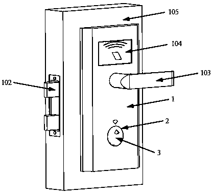
[0025] Embodiment one, such as figure 1 As shown, a schematic diagram of the overall structure of an electronic door lock with a key cover protection device installed on an electronic door lock according to an embodiment of the present invention; The mechanical lock core 106 located in the keyhole is jointly formed and installed on the door body 105 . It can be seen that the key cover 3 has covered the key hole.

[0026] It can be understood that the authorization method of the electronic door lock can also include other structures, such as adding fingerprint recognition authorization, Bluetooth connection, password keyboard, iris recognition, voice recognition, etc., the above methods are commonly used in existing electronic door locks The authorization identification mode is not limited in the present invention.

[0027] It can be understood that the electronic door lock can also include other structures, such as a vibration sensor for anti-destructive picking, a world loc...

Embodiment 2

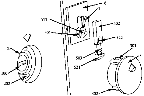
[0042] Embodiment 2. The difference between this embodiment and Embodiment 1 is that the electric control device is a miniature electromagnet 504 that stretches out the bearing after power-on, and retracts the bearing automatically after power-off. The hook 541 matched with the card slot 301; the key cover is inserted into the key hole for rotation, and is engaged with the front end of the bearing; Figure 6 Shown is a schematic diagram of the explosion structure of the electronic control device in cooperation with the key cover and key hole.

[0043] It can be seen that the limit projection 302 on the key cover in the figure is screwed into the limit groove 202 of the key hole, and the key cover is locked by engaging the slot 301 with the hook 541 at the front end of the electromagnet bearing. Unable to open.

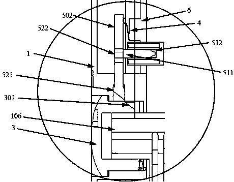
[0044] Such as Figure 7 Shown in is the cross-sectional structure diagram when the electric control device is used with the key cover and closed.

[0045] When the...

Embodiment 3

[0048] Embodiment 3. The difference between this embodiment and Embodiment 2 is that the electric control device is a miniature electromagnet 505 in which the bearing protrudes when the power is turned on, and the bearing retracts automatically when the power is turned off.

[0049] Under normal conditions, the electromagnet bearing remains retracted; when the key cover is pressed or rotated, the sensor switch will be triggered; at this time, if the electronic controller is normal, the electromagnet 505 will be energized, and the bearing will stick out and lock in. In the draw-in slot 301 on the key cover, prevent the key cover from rotating and opening; if the electronic controller fails, the electromagnet 505 does not work, and the key cover can be opened by continuing to rotate. Such as Figure 8 That is, the schematic diagram of the structure of the electric control device and the key cover of this structure, Figure 9 The cross-sectional structure diagram of the electric...


PUM


Abstract

A lock hole protecting cover device for an electronic door lock comprises a key hole 2 located in a lock body panel 1, a lock cover 3, an induction switch 4, an electronic control device 5 and an electronic controller 6, wherein the key hole is covered with the key cover, the key cover cooperates with a buckle structure in the key hole for use, the induction switch is responsible for inducting the action that the key cover is opened, the electronic controller is responsible for controlling the electronic control device, the electronic control device is responsible for clamping the key cover in the key hole so that the key cover can not be opened in the power-on state, and when the electronic controller breaks down or obtains a corresponding opening instruction, the electronic control device will not influence opening of the key hole in the power-off state. Due to the adoption of the mode, daily normal use of an existing electronic door lock is not influenced, malicious damage to the key hole can also be prevented, the key cover can be directly opened when the electronic controller breaks down, and the dual purposes that daily protection is achieved and use is not influenced after faults are achieved.

Description

technical field [0001] The invention relates to an electronic lock, in particular to a keyhole protective cover device used on an electronic door lock. Background technique [0002] Electronic door locks have been widely used in many places, and compared with traditional mechanical door locks, they have the advantage of preventing technical unlocking. Generally, electronic door locks are powered by batteries and have strict requirements on daily standby power consumption. They are often dealt with by power-off locking. Once the battery fails or the electronic components of the electronic door lock fail, the door may not be able to be opened. . Therefore, the national standard requires that the electronic door lock must have an emergency mechanical lock hole. When the electronic part fails to open the door, the mechanical lock cylinder can be opened by the mechanical key. However, since the emergency mechanical lock hole can be unlocked in any state, it has become the bigge...

Claims


Application Information

Patent Timeline
Patent Type & Authority Applications(China)
IPC IPC(8): E05B17/18E05B47/00
Inventor 徐志国
Owner WUHAN PULINGUANGTONG TECH
Why Eureka
Try Eureka