Supercharge Your Innovation With Domain-Expert AI Agents!

Variable Control Valve

A control valve, variable technology, applied in the direction of valve details, valve device, valve shell structure, etc., can solve the problems of low efficiency, complex structure, high cost, etc., and achieve the effect of simple structure and flexible installation method

Active Publication Date: 2016-08-17
BENGBU YELI MACHINERY
View PDF5 Cites 0 Cited by
  • Summary
  • Abstract
  • Description
  • Claims
  • Application Information

AI Technical Summary

Problems solved by technology

The structure is relatively complex, high cost, large energy loss, low efficiency, high heat generation, commonly used in low-voltage and low-power equipment

Method used


Image

  • Variable Control Valve
  • Variable Control Valve
  • Variable Control Valve

Examples


Embodiment Construction

[0016] The present invention will be further described below in conjunction with accompanying drawing:

[0017] see figure 1 , figure 2 and image 3 .

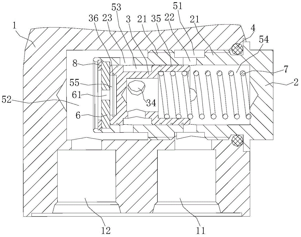
[0018] Variable variable control valve, including valve body 1, valve cover 2 and valve core 3;

[0019] The valve body 1 is a shell with one end open;

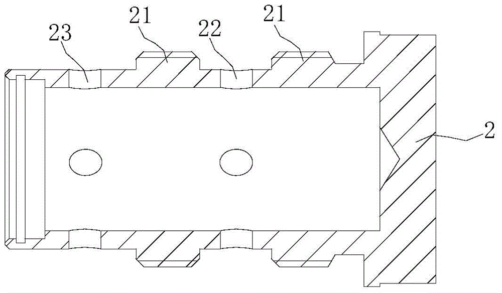
[0020] The bonnet 2 is a hollow shaft with an open end, and its outer wall is provided with two spaced shoulders 21, and the shoulders 21 are provided with external threads. There is a space between the inner walls of the opposite valve body 1, and the inner wall of the valve body 1 is provided with an internal thread that matches the external thread on the shoulder 21 at the position of the shoulder 21 of the corresponding bonnet 2, and the inner thread that matches the bonnet 2 A sealing ring 4 is installed between the other end of the valve cover 2 opposite to the opening end of the valve body 1 and the opening end of the valve body 1. The valve cover 2 and the two s...


PUM


Abstract

The variable control valve includes a valve body, a valve cover and a valve core; the valve body is a shell with one end open; Inside the valve body, the valve cover and its two shoulders divide the interior of the valve body into two chambers. The valve body is provided with an oil inlet connected to the first chamber and an oil outlet connected to the second chamber. The spool is a shaft body with a stepped hole at one end and a blind hole at the other end, and a circle of grooves on its outer wall. The third cavity is formed, the stepped hole of the valve core and the inside of the bonnet form the fourth cavity; the opening end of the bonnet is provided with a throttling piece, the fourth cavity is provided with a spring, the blind hole of the spool and the throttle piece The fifth cavity is enclosed, and a retaining ring for holes is installed on the outside of the throttle plate in the valve cover. The variable control valve provided by the invention has simple structure, flexible installation mode, and can effectively adjust the flow of liquid.

Description

technical field [0001] The invention relates to a control device of a forklift hydraulic system, in particular to a variable control valve. Background technique [0002] In the high-pressure and high-flow forklift hydraulic system, when the forklift lifting cylinder is descending, the cylinder moves at high speed under the action of the load, causing the piston to move to the end of the stroke at high speed, which often causes violent mechanical movement; similarly, high-speed movement When the piston stops suddenly, it will also cause water hammer in the pipeline in the hydraulic system, causing great impact and noise. The phenomenon caused by the high-speed movement of the piston will affect the working performance of the forklift and damage the hydraulic cylinder and hydraulic components in the forklift. Therefore, it is very necessary to install throttling and speed-regulating hydraulic components in the hydraulic system of the forklift to adjust the excessive descendin...

Claims


Application Information

Patent Timeline
Patent Type & Authority Patents(China)
IPC IPC(8): F15B13/02B66F9/22F16K27/12
Inventor 徐龙宋西华刘强强朱明杨张红霞朱琼杰蒋炼红崔岗
Owner BENGBU YELI MACHINERY
Features
  • R&D
  • Intellectual Property
  • Life Sciences
  • Materials
  • Tech Scout
  • Unparalleled Data Quality
  • Higher Quality Content
  • 60% Fewer Hallucinations
Learn More